


10.0 Installation
33
© Baxi Heating UK Ltd 2011
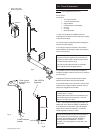
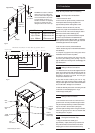
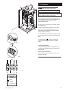
10.7 Making The Electrical Connections
WARNING: This boiler must be earthed
IMPORTANT: Four core cable is required to supply the
boiler as a permanent live is necessary for the operation
of the condensate pump and frost protection.
1. The electrical connections are on the right hand side of the
boiler. Depending upon the nature of the installation it may
be preferable to wire up to the boiler first before
manoeuvering into position.
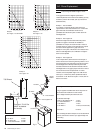
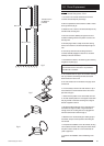
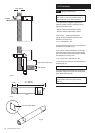
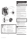
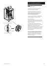
2. Undo the two screws securing the cable clamp and place
to one side (Fig. 31).
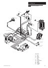
3. Route the incoming electrical cable(s) from the system
control wiring centre through the grommet in rear of the
boiler and the grommet in the support bracket. This will
prevent damage to the cable(s).
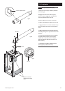
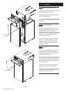
4. Lay the cable through the cable clamp to gauge the length
of wire required when it is connected to the 4-way terminal
block.
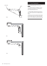
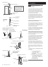
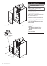
5. Connect the (S/L), ( ), (N) and (P/L) wires to the
4-way terminal block (Fig. 33) and refit the cable clamp
(Fig. 31).
INTEGRAL PROGRAMMER
If the optional integral programmer is being fitted it can be
done at this stage. Consult the instructions supplied in the
programmer kit.
Check the electrical installation for;
earth continuity, short circuits, resistance to earth, correct
polarity and fuse rating.
Fig. 33
S/L N
Fig. 32
Cable Clamp
4-way Terminal Block
P/L
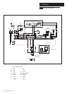
S/L
N
P/L
Switched Live
Permanent Live
Earth
Neutral
Wiring from System
Controls
Fig. 31