


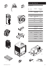

15.0 Changing Components
45
© Baxi Heating UK Ltd 2011
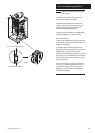
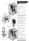
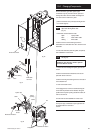
The fan and venturi, gas valve, injector pipe,
condensate trap, fan protection sensor, spark and
sensing electrodes can be accessed and changed on
the removal of the airbox door panel.
1. Remove the airbox door panel by loosening the four
1
/
4
turn screws (Fig. 50).
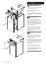
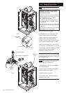
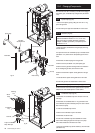
15.7 Spark and Sensing Electrodes
(Fig. 51)
1. Disconnect all three leads from tabs.
Spark - Opaque cable
Earth - Green/Yellow cable
Sensing - White cable
2. Remove the two screws securing each of the
electrodes to the combustion box door and remove the
electrodes.
3. Fit the new electrodes (and new gasket, as required)
and reassemble in reverse order.
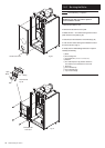
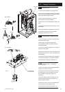
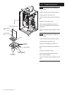
15.8 Fan (Fig. 52)
WARNING: The PCB Control and Fan
Assembly are 325 Vdc. Isolate system
controls before access.
1. Loosen the screw holding the injector pipe into the
venturi.
2. Remove the electrical connections to the fan and
protection sensor on the fan.
3. Remove the wing nuts securing the fan to the base of
the combustion box.
4. Lower the fan and remove.
5. If changing the fan, remove the screws securing the
venturi and fan protection sensor bracket, noting the
positions of the injector opening and sensor bracket, fix
them to the new fan.
6. Fit the new fan and reassemble in reverse order.
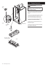
The injector pipe, condensate trap and gas valve can
be changed after the removal of
the fan.
Wing Nuts
Injector Pipe
Screw
Electrical Connections
Electrical Connection
Protection
Sensor
Injector
Opening
Gasket
Venturi
Fan
Air Box Door Panel
Sensing
Earth
Spark
Combustion
Box Door
Fig. 50
Fig. 51
Fig. 52