


10.0 Installation
29
© Baxi Heating UK Ltd 2011
Check Site Requirements before commencing.
10.1 Initial Preparation & Installation
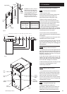
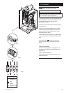
1. Remove the outer carton.
2. For the boiler to operate correctly it must be level
in both planes. Place the fixing template in the
proposed boiler position ensuring that it is level.
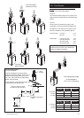
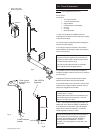
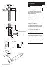
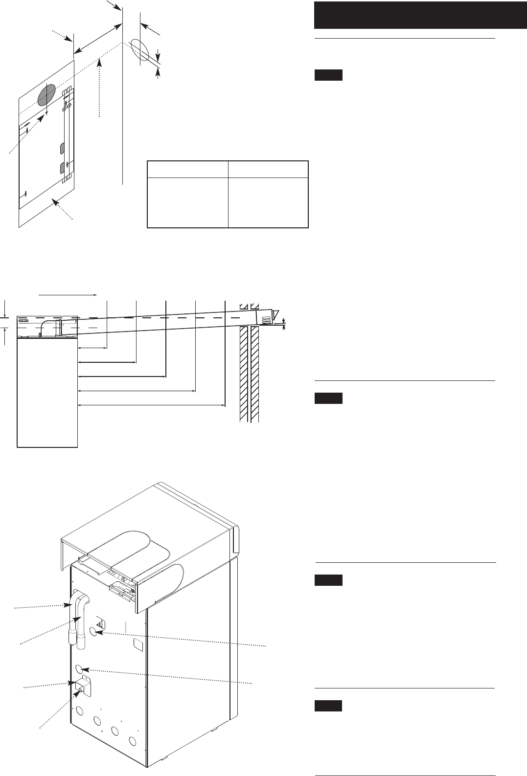
3. Mark the centre of the flue hole (rear exit).
For side exit: project the horizontal side flue centre
line into the corner of the room and along the wall to
where the flue hole will be drilled. (Fig. 20).
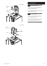
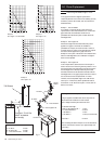
The diagram (Fig. 21) shows the dimensions required
to ensure any horizontal flue is installed with the
correct fall to the boiler. Mark the offset (V) dimension
and if required, mark the position of the gas, water and
condensate pipes. Remove the template.
4. Cut the hole for the flue (minimum diameter
125mm, see table (Fig. 20) for wall thicknesses and flue
hole diameters).
5. Complete any pipework and wiring that will be
inaccessible once the boiler is in position.
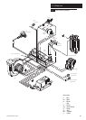
6. Undo the securing screws and remove the facia,
front door panel and top panel (see Figs. 1 & 2 on
page 6). Remove the securing screw and disengage the
pipe access panel.
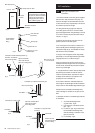
10.2 Making the Water Connections
1. If desired the flow and return tails supplied with the
boiler can be fitted at this stage and secured with the
spring clips. The flow and return connections are
identified on the boiler rear panel. The flow pipe
incorporates a manual air vent.
2. Note that the seal is made by use of an ‘O’ ring,
therefore some pipe movement will be evident even
though a water tight seal has been achieved. Excessive
force could result in damage to the connection.
3. Make all soldered joints before connecting the tails
to the boiler to avoid damaging the ‘O’ rings.
4. Refit the pipe access panel.
10.3 Making the Gas Connection
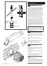
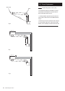
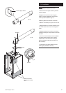
1. The connection to the boiler is a 15mm tail on the
gas service cock. The tail protrudes through the boiler
rear panel and is protected by a transit bracket which
may be removed to aid connection (see Fig. 22).
2. If solder joints are being used for the gas connection,
remove the gas tap from the valve as excessive heat
may damage the ‘O’ ring seal.
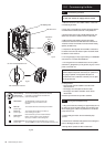
10.4 Priming the Condensate Trap
1. Using a funnel and tube, carefully pour
approximately 1 cupful (250ml) of tap water into the
flue products exhaust at the terminal or flue elbow
sampling point to ensure a seal is made in the trap.
Wall Thickness
up to 227mm
up to 750mm
up to 1200mm
Flue Hole ø
125mm core drill
150mm core drill
175mm core drill
Fig. 20
Fig. 21
Fig. 22
Horizontal
Side Flue
Centre Line
EXAMPLE: If the boiler is 2 metres
away from corner of wall the flue
duct hole will be 55mm higher than
the horizontal side flue centre line.
This will maintain an approx. 1.5°
backfall to the boiler. It is especially
important to consider this when
fitting the boiler under a work top !
Template
Edge of Boiler
0.5
1.0
2.0
3.0
4.0
V
Flue Duct Hole
OffsetV (mm)
13.5 27.5 55 82.5 110
(metres)
(mm)
1.5°
Backfall to the boiler, ie. 2m flue offset (V) position 55mm
Example
2m
Example
V = 55mm
125mm
Centre
Hole
Flow
Tail
Return
Tail
Hole for
Electrical
Cable
Gas
Connection
Hole for
Condensate
Drain Outlet
Transit
Bracket