


8.0 Flue Options
24
© Baxi Heating UK Ltd 2011
Fig. 18
Fig. 18a
Fig. 19
270mm 800mm
Push Fit Adaptor
Air Duct
Flue Duct
Cut the same
amount off the
Air Duct &
Flue Duct
Approx
1425mm
Flue Deflector
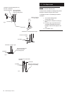
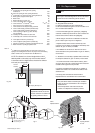
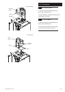
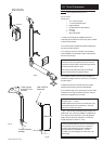
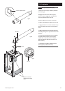
8.6 For Roof Terminals
1. In the case of a pitched roof 25 - 50 degrees, position
the lead tile to replace/flash over existing roof tiling. Make
an aperture in the roof suitable for the lower tube of the
roof terminal and ensure the integrity of the roof cover is
maintained. The adjustable plastic collar can either be
positioned on the lead tile or the lower tube of the roof
terminal prior to the final positioning of the vertical flue
through the tile. Check the collar is correctly located to suit
required roof pitch (either 25° to 38° or 37° to 50°). From
inside the roof adjust the flue to a vertical position and
secure to the roof structure with the clamp supplied.
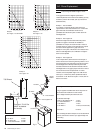
2. For flat roof installations the aluminium flashing must be
incorporated into the roof covering and the appropriate
aperture made in the roof decking. The vertical flue is
lowered onto the flashing making sure the collar of the flue
locates securely with the flashing. (A mastic seal may be
necessary). From inside the roof, adjust the flue to a vertical
position and secure to the roof structure with the clamp
supplied.
IMPORTANT: If the boiler is not fitted immediately
after the flue system, temporary precautions must be
taken to prevent rain entry into the room of installation.
Any precautionary measures must be removed prior to
commissioning the boiler.
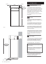
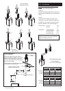
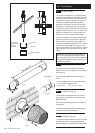
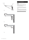
8.7 Flue Dimensions
The standard horizontal flue kit allows for flue lengths
between 270mm (10
5
/
8
”) and 800mm (32”) from elbow to
terminal (Fig. 18).
The maximum permissible equivalent flue length is: 4
metres.
NOTE: Each additional 45° of flue bend will account
for an equivalent flue length of 0.5m.
eg. 45° = 0.5m, 90° = 2 x 45° = 1m etc.
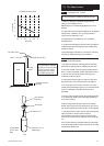
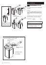
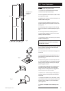
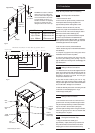
8.8 Terminal Guard (Fig. 19)
1. When codes of practice dictate the use of terminal
guards, they can be obtained from most Plumbers’ and
Builders’ Merchants.
2. When ordering a terminal guard, quote the appliance
model number.
3. The flue terminal guard should be positioned centrally
over the terminal and fixed as illustrated.
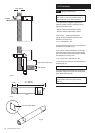
8.9 Flue Deflector (Fig. 18a)
1. If required, push the flue deflector over the terminal end
and rotate to the optimum angle for deflecting plume.
Secure the deflector to the terminal with screws provided.