


9.0 Plume Displacement
27
© Baxi Heating UK Ltd 2011
9.3 General Fitting Notes - P.D.K.
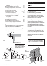
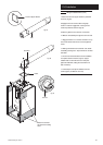
1. Cut a hole in the external wall which the horizontal
concentric flue assembly will pass through.
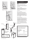
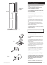
2. When completed the terminal must be at least 2 metres
above ground level (Fig. E).
3. Measure and cut to size the concentric assembly and any
extensions that are being used.
4. Insert the concentric assembly through the hole from
outside the building and mark the position of the flue trim
securing holes.
5. Drill and plug the wall to accept the flue trim securing
screws, and re-insert the concentric assembly through the
wall.
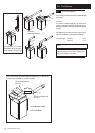
6. Connect any extensions that are being used to the
concentric assembly. Engage the extension or concentric
assembly in the boiler flue elbow.
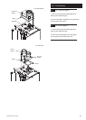
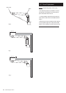
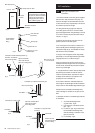
7. Fit the boiler flue elbow to the boiler top panel, ensuring
the gasket is in place (Fig. F).
Ensure that the concentric assembly is horizontal and that
the external air inlet is to the bottom. Any extensions
should fall back to the boiler.
8. Use suitable brackets to support the concentric assembly
and any extensions, and make good inside and outside.
Secure the flue trim to the wall.
9. The 70Ø exhaust can now be fitted to the spigot at the
terminal end.
10. If it is necessary to shorten the 70Ø exhaust or any of
the extensions, the excess material must be cut from the
plain end of the pipe.
11. Determine the position of the 70Ø exhaust and mark
on the wall a suitable position for the support bracket. Drill
and plug the wall. If extensions are being used, a support
bracket is supplied in each kit.
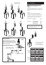
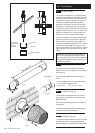
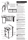
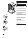
12. Engage the M6 threaded part of the mounting bolt in
the boss on the support bracket. Using the bracket for
leverage, screw the mounting bolt into the plugged hole
until the bracket is secure and level (Fig. G).
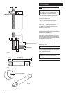
13. Slacken the two screws securing the retaining strap to
the bracket, and pivot the strap aside to allow fitting the
70Ø exhaust.
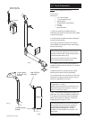
14. Complete the installation of the 70Ø exhaust, securing
in the brackets. Fit the 93° elbow and plume outlet. Ensure
the plume outlet is at least 45° to the wall and that the
‘peak’ is uppermost.
15. Continue with installation and commissioning of the
boiler.
Min. 2 metres
This section of the
flue MUST be
horizontal
Min. 0.3 metres
Fig. E
Fig. F
Fig. G