


14.0 Servicing the Boiler
41
© Baxi Heating UK Ltd 2011
14.2 Annual Servicing - Inspection (Cont)
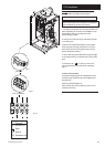
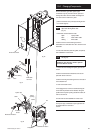
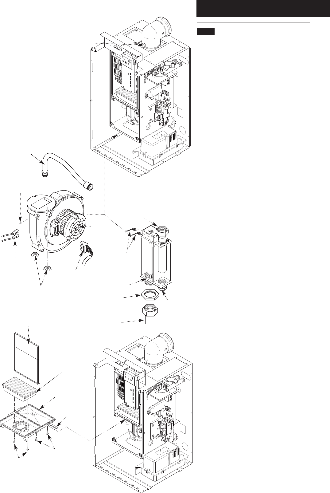
7. To clean the heat exchanger and burner proceed as
follows:
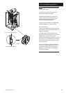
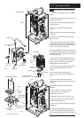
a) Disconnect the electrical leads to the fan component
protection sensor (Fig. 42).
b) Loosen the screw retaining the gas injector pipe at
the venturi (Fig. 42).
c) Undo the two wing nuts to disconnect the fan
(Fig. 42).
d) Remove the fan and disconnect the electrical supply
to it (Fig. 42).
e) Remove the gas injector pipe from the gas valve
(push-fit) (Fig. 42).
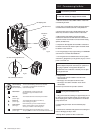
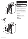
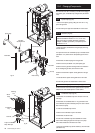
f) Remove the condensate trap drain plug and place a
vessel underneath to catch the condensate (care should
be taken as this could be hot). The condensate drain
pipe may be removed to increase access.
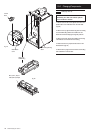
g) Undo the condensate trap securing nut, lock nut and
the condensate drain pipe. Remove the condensate trap
and disconnect the sensor leads (Fig. 43). Clean the trap
and refit the drain plug.
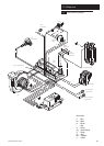
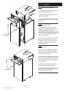
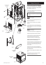
h) Remove the two screws securing the burner and
remove the burner. Visually inspect the internal burner
baffle for obstruction, check seal around baffle for
cracks/damage. Clean with a soft brush.
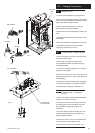
i) Loosen the two screws retaining the heat exchanger
support bracket and slide to the left to remove
(Fig. 44).
j) Remove the four screws securing the heat
exchanger/combustion box base and withdraw the
base.
k) Lower the central insulation panel and check
condition (Fig. 44). Replace the lower insulation pad if
necessary.
l) Ensure the heat exchanger fins are clear of any
obstruction.
m) Check condition of all seals. Important: Pay
particular attention to the condition of the
combustion box door seals.
n) Reassemble in reverse order and check for leaks.
8. Check the operation of the condensate pump and
drain pipework (see Section 10.1)
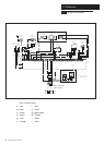
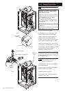
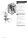
9. Check CO/CO
2
ratio at flue sampling point (Fig.41a).
See section 4.0.
10. Complete the relevant Service Interval Record
section of the Benchmark Commissioning Checklist at
the rear of this publication and then hand it back to the
user.
Combustion Box Base
Securing Screws
Burner Securing
Screws
Combustion
Box Base
Burner
Wing Nuts
Electrical Supply
Lock Nut
Condensate
Trap
Trap to Condensate
Pump Inlet Pipe
Securing Nut
Central Insulation Panel
Heat Exchanger
Support Bracket
Injector Pipe
Injector Pipe Retaining
Screw
Protection
Sensor Leads
Fan
Fig. 42
Fig. 44
Fig. 43
Sensor
Leads
Flue Sampling Point
Fig. 41a
Service Drain
Plug