


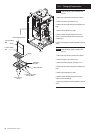
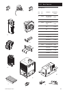
15.0 Changing Components
44
© Baxi Heating UK Ltd 2011
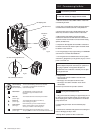
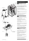
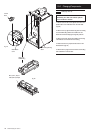
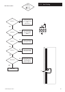
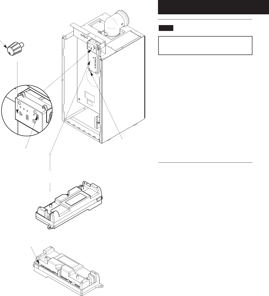
15.6 PCB (Figs. 48 & 49)
WARNING: The PCB Control and Fan
Assembly are 325 Vdc. Isolate system
controls before access.
1. Pull the control knob off the spindle and remove the
plastic button cover. Refit them onto the new PCB
(Fig. 48).
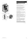
2. Remove the top right hand securing screw and swing
out the PCB housing. Remove the PCB cover and
disconnect the electrical plugs noting their positions
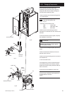
3. Remove the screw securing the PCB to the housing.
The PCB can be removed from the housing.
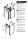
4. Ensure that the two jumpers are fitted to the new
PCB as shown (Fig. 49).
5. Reconnect the plugs, fit the new PCB to the housing
and reassemble in reverse order.
PCB Housing Securing
Screw
Control
Knob
Fig. 48
Fig. 49
Hinge open
PCB Housing
Plastic Button
Cover
Blue (CN11) Jumper
Red (CN12) Jumper