


6.0 System Details
14
© Baxi Heating UK Ltd 2011
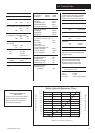
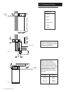
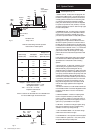
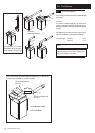
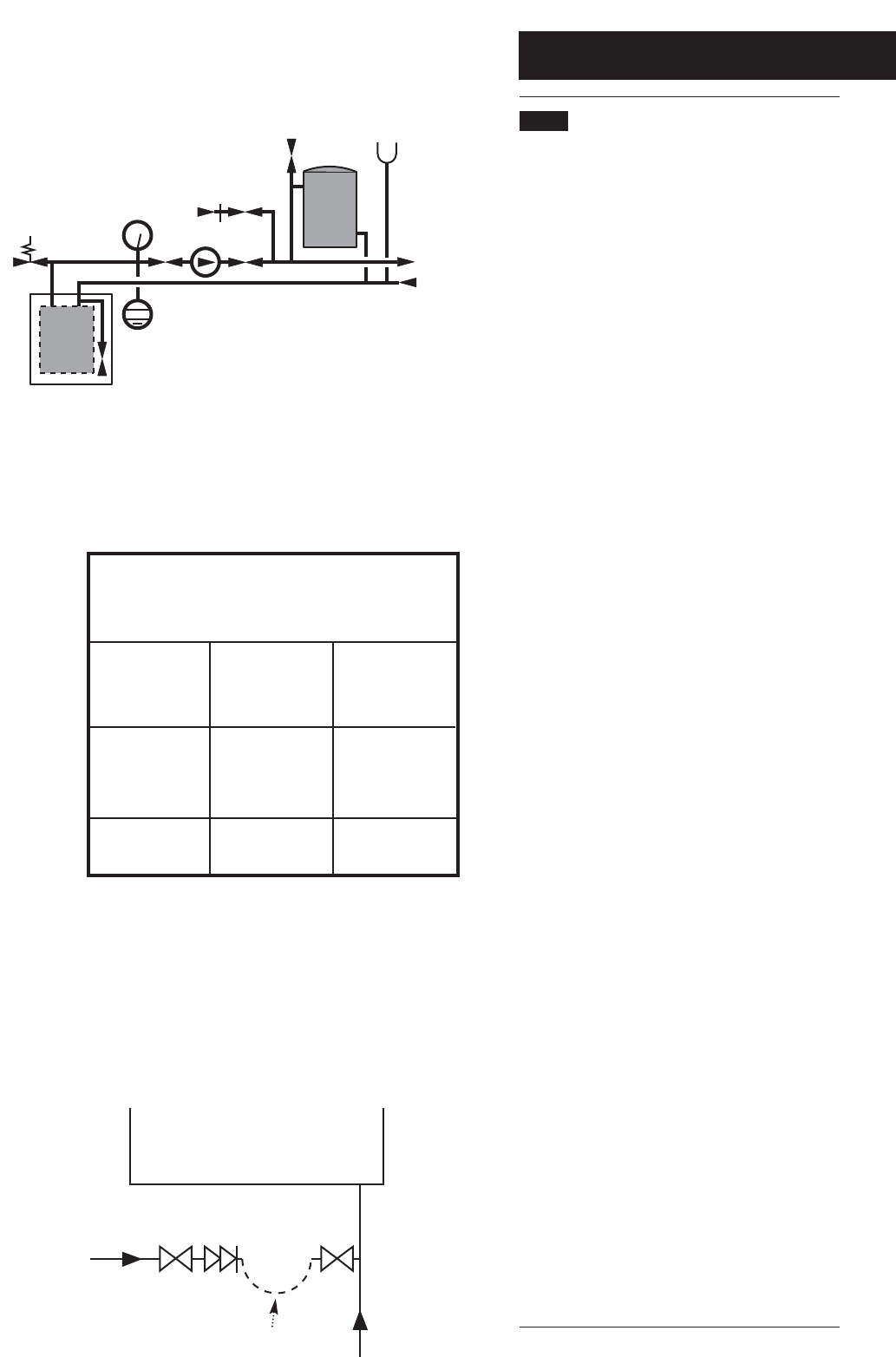
6.7 Sealed Systems (Fig. 13)
1. SAFETY VALVE - A safety valve complying with the
requirements of BS 6750 Part 1 must be fitted close to
the boiler on the flow pipe by means of a horizontal or
vertically upward connection with no intervening valve
or restrictions and should be positioned to facilitate
testing. The valve should be pre-set and non-adjustable
to operate at a pressure of 3 bar (45 Ibf/in
2
). It must be
arranged to discharge any water or steam through a pipe
to a safe outlet position.
2. PRESSURE GAUGE - A pressure gauge of minimum
range 0-4 bar (0-60 Ibf/in
2
) with a fill pressure indicator
must be fitted to the system, preferably at the same
point as the expansion vessel in an easily visible position.
3. EXPANSION VESSEL - An expansion vessel
complying with the requirements of BS 4814 must be
fitted to the system by means of a connection close to
the inlet side of the circulating pump in accordance with
the manufacturers instructions, the connecting pipe being
unrestricted and not less than 15mm (
1
/
2
in) nominal size.
The volume of the vessel should be suitable for the
system water content and the nitrogen or air charge
pressure should not be less than the system static head
(See Table. 1).
Further details of sealed system design can be obtained
from BS 5449 and the British Gas publication entitled
'Specifications for Domestic Wet Central Heating
Systems'.
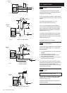
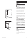
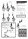
4. FILLING POINT - A filling point connection on the
central heating return pipework must be provided to
facilitate initial filling and pressurising and also any
subsequent water loss replacement / refilling. The sealed
primary circuits may be filled or replenished by means of
a temporary connection between the primary circuit and
a supply pipe provided a ‘Listed’ double check valve or
some other no less effective backflow prevention device
is permanently connected at the inlet to the circuit and
the temporary connection is removed after use. The
filling method adopted must be in accordance with all
relevant water supply regulations and use approved
equipment.
Your attention is drawn to, for GB: Guidance G24.2 and
recommendation R24.2 of the Water Regulations Guide.
for IE: the current edition of I.S. 813 “Domestic Gas
Installations”.
5. MAKE UP SYSTEM - A method of replacing water
lost from the system should be provided either by
means of a make up vessel of not more than 3 litres (5
pints) capacity, mounted above the highest point of the
system, or by re-pressurisation of the system.
6. VENTING - A method of venting the system during
filling and commissioning must be provided by fitting
automatic air vents or by venting manually.
7. HOT WATER STORAGE - The hot water storage
vessel must be of the indirect coil type.
8. COMPONENTS - All components used in the system
must be suitable for operation at 110°C (230°F) and at
the pressure allowed by the safety valve.
Safety
Valve
Pressure
Gauge
Pump
Filling
Point
Air
Vent
3 Litre
Top Up Bottle
(if required)
Radiator
Circuit
Expansion
Vessel
System Drains at
Low Point
Max Boiler Flow
Temp = 82° C
Boiler
Fig. 13
Table. 1
Vessel Charge
Pressure (Bar)
0.5
1.0
1.5
Initial System
Pressure (Bar)
0.5
1.0
1.5
2.0
1.0
1.5
2.0
1.5
2.0
Multiply Total
Water Content Of
System By (Litres)
0.067
0.112
0.207
0.441
0.087
0.152
0.330
0.125
0.265
Method of determining minimum expansion
vessel volume for sealed systems.
System Volume = 75 litres
Vessel Charge Pressure = 1.0 bar
Initial System Pressure = 1.5 bar
75 x 0.152 = 11.4 litres
Expansion Vessel Volume
Example :-
Then :-
NOTE
Where a vessel of the calculated size is not obtainable then
the next available larger size should be used.
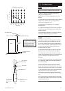
Stop
Valve
Double
Check
Valve
Mains
Inlet
CH
Return
Temporary
Hose
Stop
Valve
Fig. 14