


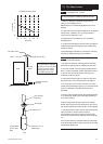

7.0 Site Requirements
17
© Baxi Heating UK Ltd 2011
7.6 Condensate Drain - General
Failure to install the condensate discharge pipework
correctly will affect the reliable operation of the boiler.
1. Ensure the discharge of condensate complies with any
national or local regulations in force.
BS 6798 & Part H1 of the Building Regulations give further
guidance.
2. If any further drain pipe is required (additional to that supplied
with the boiler), it should be run in a proprietary material
e.g. PVC, PVC-U, ABS, PVC-C or PP.
3. Metal pipework is NOT suitable for use in condensate
discharge systems.
4. Any pipe fitted externally must be kept as short as possible to
minimise the potential of freezing and must be insulated using
waterproof material.
5. When discharging condensate into a soil stack or waste pipe
the effects of existing plumbing must be considered.
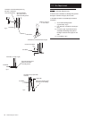
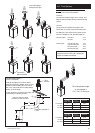
7.7 Condensate Disposal
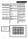
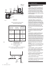
1. This boiler incorporates an automatic pumped condensate
system. See the graph opposite for available pump flow rates.
2. 3.5 metres of flexible 10mm PVC pipe are supplied with the
boiler. 0.5 metres of this length remains coiled within the boiler
to allow removal of the pump assembly. This must not be
uncoiled to provide extra length.
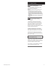
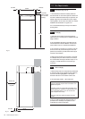
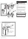
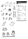
3. A fitting and securing clip (Fig. B) to accept the 10mm PVC
pipe and connect to 21.5mm overflow pipe is also supplied.
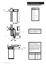
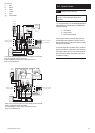
4. The 10mm pipe can be routed to a maximum of 3 metres
vertically and then discharge via gravity or be routed horizontally
(Fig. A). A combination of vertical and horizontal runs is
permissible.
5. The pipe must be supported, either using suitably spaced clips
or run within larger diameter pipe. When using clips take care
not to deform the pipe.
6. When routing the pipe through a wall it must be suitably
sleeved. Also the pipe must not be exposed to sources of heat,
and should be protected in locations where it may be damaged.
7. The pipe should be routed so that any sharp bends, dips and
loops are avoided. A minimum radius of 100mm is
recommended for any bends. No slope is necessary and air
breaks are not required on the pumped part of the condensate
run.
8. If the boiler is fitted in an unheated location the entire length
of condensate pipe should be treated as external, and run within
insulated larger diameter pipe.
1
2
3
4
0
1.5
2
3
4
2.5
3.5
Flow (l/min)
Head (metres)
Boiler
Max. Head
3 metres
Alternative Horizontal
Discharge
Gravity Drain min. fall 3°
Min. radius 100mm
Condensate Pump Flow Graph
Fig. A
Note: The point of discharge from
the pumped length of condensate
pipe (point ‘A’) must not be below
the level of the pump, whether
discharging direct into a drain or
into an additional gravity drain.
10mm PVC Pipe
(8.5mm I.D.)
21.5mm Ø O.D. to fit
Overflow Pipe
8.5mm Ø O.D.
Condensate Pipe
Direct Connect
Fitting
Point ‘A’
Securing Clip
Fig. B