


15.0 Changing Components
46
© Baxi Heating UK Ltd 2011
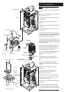
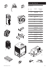
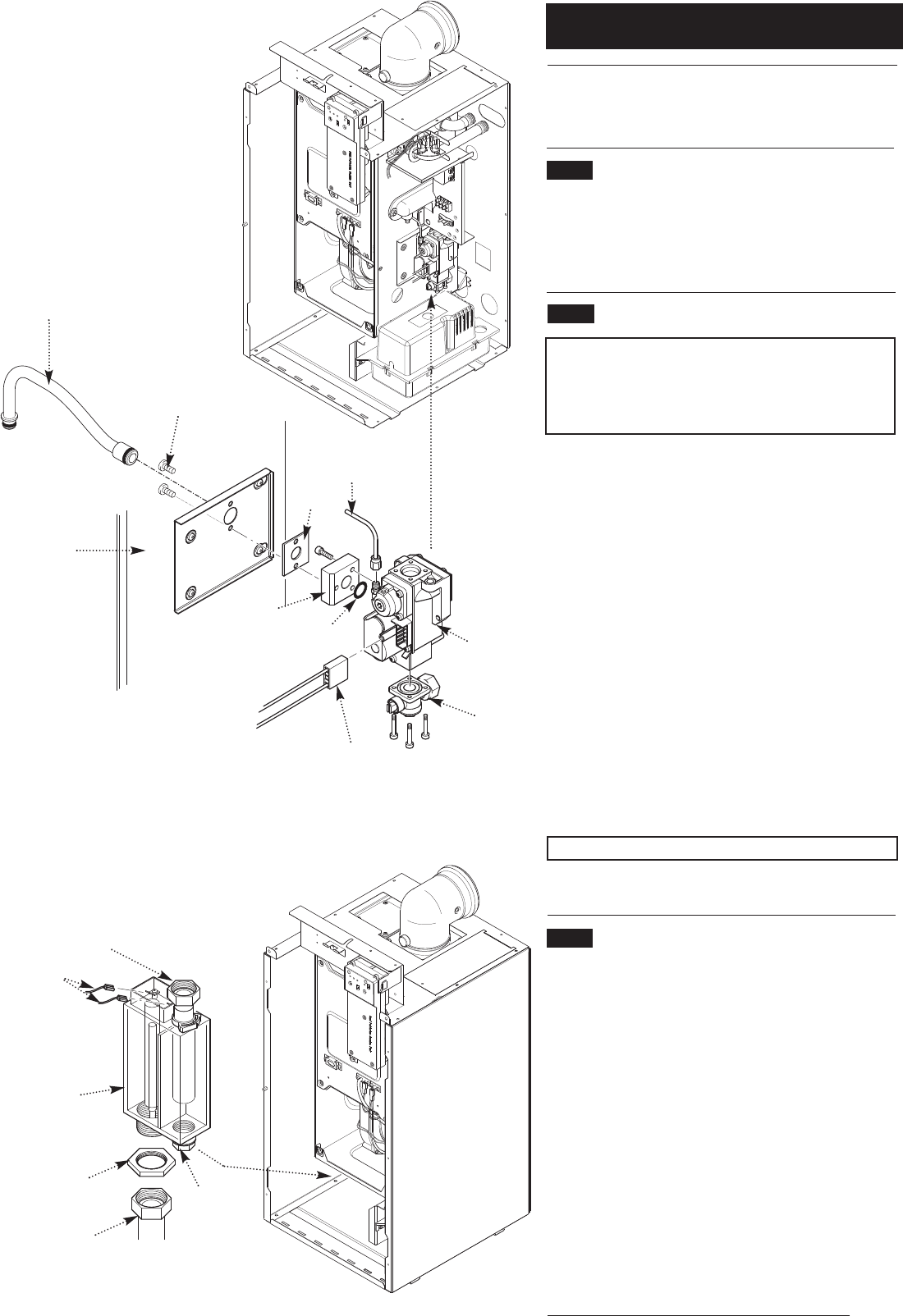
The removal of the fan is necessary to enable the changing of
the injector pipe, condensate trap and gas valve (see section
13.6).
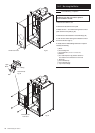
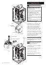
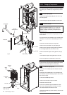
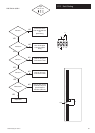
15.9 Injector Pipe (Fig. 53)
1. Remove the injector pipe by pulling out from the ‘O’ ring
joint in the gas valve.
2. Fit the new injector pipe and reassemble in reverse order.
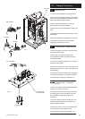
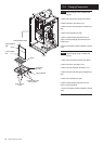
15.10 Gas Valve (Fig. 53)
IMPORTANT: After replacing the valve the CO
2
must be
checked as detailed in Section 14.1.4 to 14.1.6. Only
change the valve if a suitable calibrated combustion
analyser is available, operated by a competent person -
see Section 14.1.3.
1. Isolate gas supply and disconnect the gas tap by removing
the four screws.
2. If required remove the condensate pump to increase access
(see Section 13.4) and undo the case pressure pipe from the
valve.
3. Disconnect the electrical plug from the gas valve.
4. Remove the fan (see Section 13.6) and injector pipe.
5. Remove the two gas valve securing screws from inside the
air box holding the gas valve, and remove the valve.
6. Remove the aluminium spacer and its gasket from the gas
valve.
7. Fit the aluminium spacer and its gasket to the new valve.
8. Fit the new gas valve and reassemble in reverse order.
NOTE: Check for gas tightness after replacing gas valve.
9. Check the CO
2
level. If the level is greater than that quoted,
telephone the Technical Enquiries for further advice.
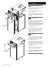
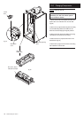
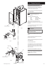
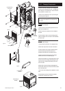
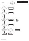
15.11 Condensate Trap (Fig. 54)
1. Disconnect the condensate trap from the base of the heat
exchanger.
2. Disconnect the condensate drain ‘O’ ring connection from
the condensate trap and condensate pump. For ease of access
also remove the pump.
3. Undo the condensate trap lock nut.
4. Remove the condensate trap from the boiler.
5. Disconnect the sensor leads.
6. Fit the new condensate trap and reassemble in reverse
order. When refitting the pipe from the trap to the pump
ensure that all seals and connections are made.
7. Prime the condensate trap (fill first chamber), check for leaks
(see Section 8.5).
Injector Pipe
Gas Tap
Case Pressure Pipe
Boiler Side
Gas Valve
Gas Valve
Securing Screws
Lock Nut
Condensate
Trap
Securing
Nut
Sensor
Leads
Fig. 53
Fig. 54
Aluminium
Spacer
‘O ring’
Gasket
Electrical Plug
Service Drain
Plug
Trap to Condensate
Pump Inlet Pipe