


9.0 Plume Displacement
25
© Baxi Heating UK Ltd 2011
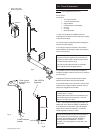
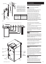
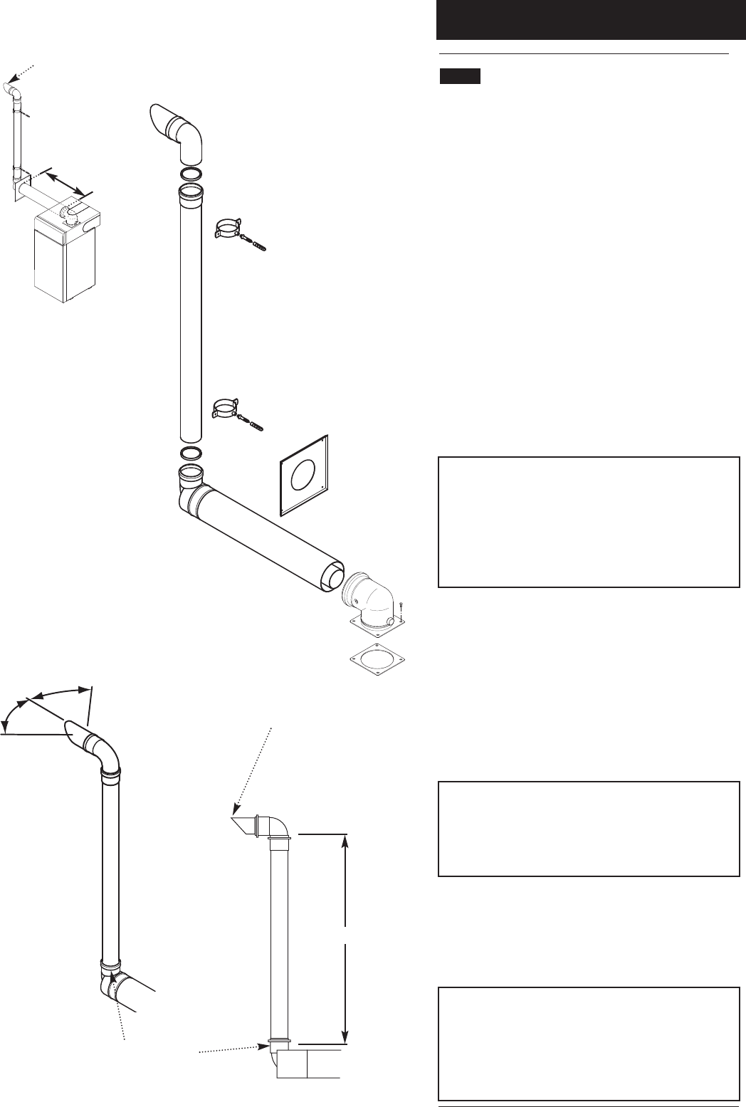
9.1 Plume Displacement Kit (P.D.K.)
Kit No 5121371
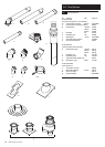
Content of kit
1 70/110 Concentric Flue
1 1m 70 Dia Exhaust Flue Pipe
2 Support Brackets
1 93° Elbow/Plume Outlet Assembly
1 Flue Trim
2 “O” Rings
1 Elbow with Gasket
1. This kit is recommended for installations where the
condensate plume emitted from the flue may cause a nuisance
or affect the surroundings.
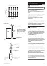
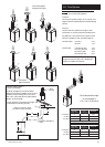
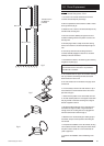
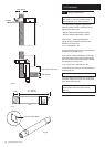
2. The terminal must be positioned outside the building with
the outlet connection upwards.
3. The 70Ø pipe connects to the outlet of the concentric
terminal assembly. The elbow/plume outlet must be fitted to
the end of the 70Ø pipe.
NOTE: The plume outlet must always be at least 45° to
the wall, with the ‘peak’ uppermost to prevent rain entry
(Figs. A & B), and be at least 2 metres above ground level.
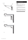
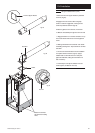
It must be secured as shown in Fig. C.
The outlet must be positioned so that any condensate
plume is directed away from adjacent surfaces.
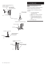
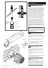
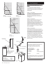
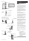
4. It is possible to reduce or increase (with the addition of
extensions) the length of either or both the 70/110 concentric
and 70Ø exhaust.
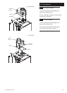
5. Standard concentric flue extension kits may be added
between the boiler elbow and the terminal assembly.
6. The minimum length of the concentric flue is 100mm when
measured from the edge of the boiler flue elbow. There is a
further 45mm engagement into the elbow.
IMPORTANT: The maximum equivalent length of
concentric flue is:- 4 metres
Additional elbows may be fitted in the concentric flue, but
the equivalent length must be reduced by 1 metre (93°
elbow) or 0.5 metres (45° elbow).
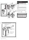
7. 70Ø 1 metre extensions (including support bracket), and
additional 93° & 45° elbows are available. Any additional 93°
& 45° elbows must be accounted for when calculating flue
lengths. 70Ø 93° elbows are equivalent to 3.5 metres of
straight length and 45° elbows to 1 metre.
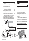
NOTE: Permitted positions of the plume outlet relative to
doors, windows etc. are the same as for conventional
concentric flues as detailed in the main Installation &
Servicing Instructions and BS5440 Pt. 1. It is NOT
necessary to fit a terminal guard over the air inlet or the
plume outlet.
Outlet Connection
upwards
‘Peak’ MUST be
Uppermost
Fig. A
Fig. B
500mm Min.
45°
45°
Outlet must be
at least 45° from
wall face
Plume Outlet (‘Peak’
MUST be Uppermost)
0.94 metre
Fig. C