


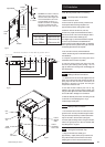

12.0 Commissioning the Boiler
36
© Baxi Heating UK Ltd 2011
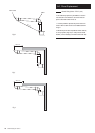
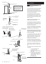
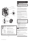
IN OUT
Gas Service
Cock
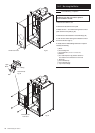
Fig. 34
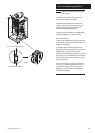
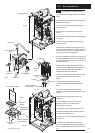
Fig. 35
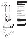
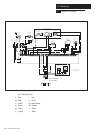
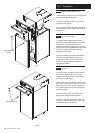
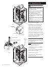
Fig. 36
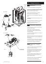
Open
Inlet Gas Pressure Test Point
DO NOT check gas pressure here
Low
High
Reset
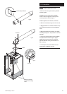
Central Heating
Control Knob
(No OFF Position)
Turn the Central Heating Control Knob clockwise
to increase or anticlockwise to decrease the
boiler flow temperature.
Reset Button
The Reset Button should extinguish the
Flame Failure Light and restore normal
operation.
Mains On
(Green Light)
This indicates that there is electricity to the Boiler.
Burner On
(Green Light)
This indicates that the Burner has fired up
and is heating your system.
Flame Failure
(Red Light)
If Flame Failure Light is ON. Press the Reset
Button. If Flame Failure occurs persistently
consult your Installer or Service Engineer.
Condensate Pump
(Green Light)
This indicates that the Condensate Pump is running.
The pump ONLY runs when the condensate reservoir is full.
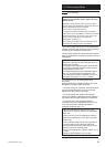
Fig. 36a
Flue Sampling Point
Manual Air Vent
12.1 Commissioning the Boiler
WARNING: The PCB Control and Fan Assembly
are 325 Vdc. Isolate at supply before access.
1. Reference should be made to BS:EN 12828 & 14336 when
commissioning the boiler.
2. At the time of commissioning, complete all relevant sections
of the Benchmark Checklist at the rear of this publications.
3. Flush the whole system using a suitable flushing agent (see
Section 6.2) and vent the radiators. Check for water leaks.
4. Refill the system with inhibitor following the inhibitor
manufacturer’s instructions and BS 7593 Code of Practice for
Treatment of Water in Domestic Hot Water Central Heating
Systems (see Section 6.2).
5. Complete the label supplied with the inhibitor and attach to
the inside of the boiler case. Detail of system treatment should
be added for future reference.
6. Turn the gas supply on and purge according to in GB BS 6891
and in IE I.S. 813 “Domestic Gas Installations”.
7. Turn the gas service cock anticlockwise to the ON position
and check for gas tightness up to the gas valve (Fig. 34). Turn the
power to the boiler ON.
IMPORTANT: The combustion for this appliance has been
checked, adjusted and preset at the factory for operation on
the gas type specified on the appliance data plate. No
measurement of the combustion is necessary. Do not adjust
the air/gas ratio valve.
8. Having checked:
•That the boiler has been installed in accordance with
these instructions.
•The integrity of the flue system and the flue seals.
•The integrity of the boiler combustion circuit and the
relevant seals.
Proceed to put the boiler into operation as follows:
12.2 Priming the Condensate Pump
1. Using a funnel and tube, carefully pour approximately 1litre of
tap water into the flue products exhaust at the terminal or flue
elbow sampling point to fill the trap and allow the condensate
pump reservoir to fill.
2. Continue filling with water until the condensate pump
operates.
3. Check that the condensate drain pipework is not leaking and
that it is discharging correctly to drain.
4. See Fig. 36a for operation of LEDs on boiler facia.