


9
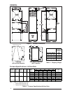
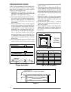
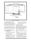
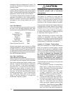
Figure 6. Closet or Alcove
10"
23 -1/4"
FLOOR
OPENING
C
L
C
L
ALT. FUEL
LINE HOLES
SIDE WALL
REAR WALL
FUEL LINE
HOLE
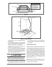
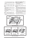
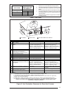
Figure 5.
X
SEE
TABLE 5
REDUCER
FELT-SEAL(
1
)
SPACERS
C
( )OPENING TO DUCT
(1) WITH PLATE (C) REMOVED
OPENING BECOMES
13-1/4” x 13-1/4”
(2) WITH PLATE (C) REMOVED
OPENING BECOMES
13" X 13". WITH REDUCER
IT IS 13" X 10-1/8".
(1) FINGER TAB DUCT CONNECTOR ONLY
(2) SCREW DOWN DUCT CONNECTOR ONLY
i. Gas piping is not run in or through the return
duct system.
j. Test the negative pressure in the closet with
the air-circulating fan operating at high speed
and the closet closed. The negative
pressure is to be no more negative than
minus 0.05 inch water column.
k. For floor return systems, the manufactured
home manufacturer shall affix a prominent
marking on or near the appliance where it
can be easily read when the closet door is
open. The marking shall read:
!
CAUTION:
HAZARD OF ASPHYXIATION: Do not
cover or restrict return air opening.
l. Air conditioning systems may require more
duct register and open louver area to ob-
tain necessary airflow. Use NORDYNE’s
certiduct program to determine proper duct
size for A/C.
DUCTED RETURN AIR
M3 furnaces with model numbers ending in AW
or BW are factory configured for the return air
to flow through the front louvered door. The
return air may also be attached to either side or
the top of the furnace cabinet using a field
installed kit. Refer to Table 12 for the NORDYNE
ducted return kit P/N number. The location and
size of the side and top return air connections
are shown in Figure 1. The filter size for the side
return air is 20” x 20” x 1”. For top return the
filter size is 24” x 16” x 1”.
M3 furnaces with model numbers ending in
BWT are factory configured for the return air to
enter the top of the furnace.