


3
Application
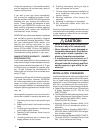
M-Manufactured Home
Furnace Series
Comfort Model
RL - Condensing Downflow
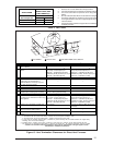
M 3 R L - 060 A - A W
Door Color
W - White
G - Gray
Cabinet Dimensions
A - 56" x 19-3/4" x 23-3/4”
B - w/Coil Cavity,
76" x 19-3/4" x 23-3/4"
Electrical Code
A - 1PH, 60 Hz, 120 VAC
Conversion .............................................. 21
Lighting and Adjustment
of the Appliance .............................. 23
Electrical Wiring ...................................... 24
Line Voltage Wiring ........................... 24
Low Voltage Wiring ........................... 26
Ventilation ................................................ 26
Start-up and Adjustment ........................ 26
Start-Up Procedure ........................... 26
Shut Down Procedure ....................... 27
Verifying and Adjusting Firing Rate ... 27
Temperature Rise ............................. 27
Verifying and Adjusting
Verifying Burner Operation.............. 28
Verifying Operation of the
Supply Air Limit Switch ................. 28
Description of Components ................ 29
Furnace Accessories............................. 29
Maintenance ........................................... 29
Combustion Air and Vent System .... 29
Air Filter(s) ....................................... 29
Lubrication ........................................ 30
Condensate Drain Assembly ........... 30
Blower Compartment ....................... 30
Heat Exchanger and Burner
Maintenance .................................. 30
System Operation Information............. 30
Sequence of Operation .................... 30
Furnace Fails to Operate ................. 31
Location of Major Components .......... 32
Wiring Diagram ....................................... 33
Installation/Performance
Checklist ......................................... 35
General ...................................................... 4
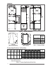
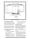
Unit Dimensions .................................. 4
Shipping Weights................................ 4
Furnace Specification ........................ 4
Air Flow Data ..................................... 4
Owner's Information ................................ 5
Installation Requirements ...................... 6
Location .............................................. 7
Clearance ........................................... 7
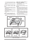
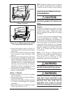
Circulating Air Supply ............................ 7
Return Air Provisions.............................. 8
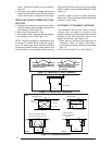
Air Distribution Systems ........................ 9
Duct Connector Selection .................... 10
Duct Installation .................................... 10
Venting and Combustion
Air Requirements ........................... 13
Venting Requirements .......................... 14
Vent Table ........................................ 15
Vent Pipe Material ............................ 16
Vent Pipe Length and Diameter ....... 16
Vent Pipe Installation ........................ 16
Pipe Routing & Support .................... 16
Location of Outdoor Termination ..... 16
Horizontal Venting ............................ 18
Vertical Venting................................ 18
Vent Freezing Protection ................. 19
Concentric Vent Termination ........... 19
Drainage of Condensate
From Furnace................................ 19
Gas Supply and Piping ......................... 20
Leak Check ....................................... 21
High Altitude Derate ......................... 21
Pressure Switch .............................. 21
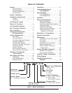
TABLE OF CONTENTS
Table 1. Model Identification
Return Air Configuration
Blank - Front
T - Top
Heating Capacity
Input, BTUH (000’)