


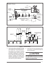
25
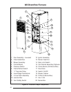
Field Supplied Disconnect
Within Sight of Furnace
Field Supplied
Panel Connector
Field Supplied
Fused Service
Panel
Black (Hot)
White (Neutral)
Green or Bare
(Ground)
Black
White
Black
White
Black
White
Field Line Voltage
Wiring
Factory Line
Voltage Wiring
Ground
Ground
Ground
Junction Box (may be internal
or external to the furnace). These
connections can be made in the
field supplied disconnect at the
furnace.
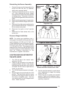
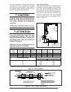
Figure 26. Line Voltage Field Wiring
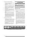
Table 10. Electrical Data
* Time-delay fuses or HACR-type circuit breakers are required.
Furnace Cabinet Nominal Maximum Minimum Maximum Minimum Maximum
Input Width Electrical Operating Operating Furnace Wire Fuse or Circuit
(Btuh) (in.) Supply Voltage Voltage Amperes Gauge Breaker Amps*
60,000 19.75 115-60-1 127 103 9.7 14 15
80,000 19.75 115-60-1 127 103 9.7 14 15
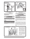
Thermostat Wire Gauge
Recommended Thermostat Wire Length
2-wire
(
heatin
g)
4 or 5-wire
(
coolin
g)
24
22
20
18
55 ft.
90 ft.
140 ft.
225 ft.
25 ft.
45 ft.
70 ft.
110 ft.
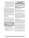
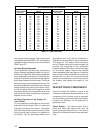
R C Y G W
Flame Signal
Light (Yellow)
60
90
120
180
TWIN
3 Amp Fuse
COM
24 V
HUM
Neutrals
41
52
63
7
8
9
4
5
6
1
2
3
EAC
HUM
M1
M2
M3
COOL
HEAT
L1
XFMR
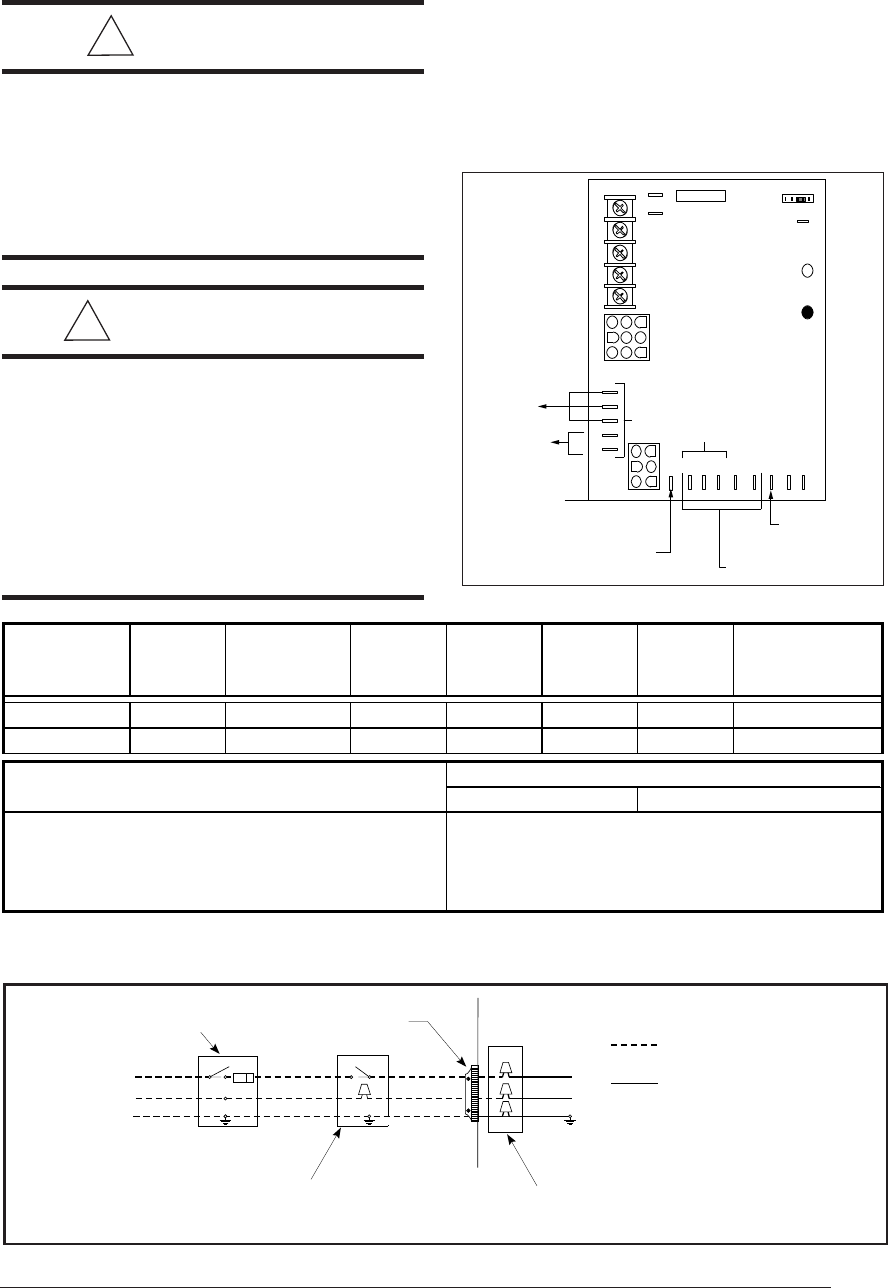
Unused Motor
Leads
EAC
Electronic Air Tap
(.5A@ 120 VAC)
Status
Light (Red)
Humidifier Tap
(.5A@ 120 VAC)
Connect
Neutral
Lead of
Electronic
Air Cleaner
and/or Humidifier
Here.
Common
Leads
Blower Off
Timing
These motor speed taps are
not used for two-stage models
Figure 27. Blower Speed Tap Location
tral line is connected to the white wire and the
incoming "hot" line is connected to the black
wire in the furnace junction box. The furnace will
not operate unless polarity and ground are
properly connected. See Figure 26.
!
CAUTION:
Label all wires prior to disconnection
when servicing controls. Wiring errors
can cause improper and dangerous
operation.
Verify proper operation after servicing.
!
ATTENTION:
Lors des opérations d'entretien des
commandes, étiqueter tous les files
avant des les déconnecter. Toute erreur
de câblage peut être une source de
danger et de panne.
S'assurer du bon fonctionnement de
l'appareil après tout entretien.
Low Voltage Wiring
Install the thermostat per the manufacturer's
instructions. The low voltage (24 volt) connec-
tions from the thermostat are made at the
terminal strip on the control board in the furnace.
See Figure 28 for the proper connections for
heating only (two-wire) and heating/cooling
(four-wire) applications. The recommended
minimum wire gauge for thermostat wiring is
shown in Table 10.