


18
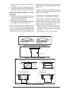
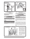
Horizontal Venting
Vent and combustion air intake terminations
must be as shown in Figure 19 unless the
concentric vent termination kit is used.
!
WARNING:
Ensure that the combustion air vent and
the exhaust vent are configured as
shown in Fig. 19. Improper vent
termination can cause recirculation of
the flue gases. This may result in furnace
vibration. In severe cases, the furnace
will cycle, due to the intermittent contact
between the flame and the flame sensor.
If you note these oscillations occurring,
check the vent configuration. Make sure
that the exhaust vent does not have a 90
degree termination.
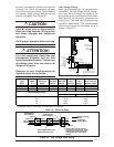
For horizontal venting, either the Horizontal
Exterior Vent Mounting Kit or the Concentric
Vent Termination Kit may be used (See Table
12).
For Canadian installations please refer to the
Canadian Installation Code (CAN/CGA-B149.1
or 2) and/or local codes.
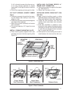
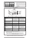
The Horizontal Exterior Vent Mounting Kit con-
sists of two face plates and an insulating gas-
ket to seal the exterior surface. A hole sized
closely to the pipe diameter must first be cut
through the wall. A short length of pipe is then
cut such that it can penetrate the wall and be
held in place by closely fitting standard cou-
plings. The face plates are retained on both
sides of the wall by the couplings, and the
gasket is retained against the wall by the outer
face plate. Face plates must be fastened to the
wall and the outside one must be flashed as
appropriate to prevent entry of water.
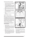
When the above kits are not used the following
steps are required:
1. Check the hole size cut through the exte-
rior wall. Insure that the hole diameter is
less than the diameter of the couplings to
be used.
2. Extend the vent pipe through the wall
approximately 1" and seal the area be-
tween the wall and pipe.
3. Apply couplings to the vent pipe on the
interior and exterior sides of the wall to
insure the pipe can not be pushed or pulled
through the wall.
4. Insure the combustion air inlet pipe has a 90
degree termination elbow, and is pointing
downward as shown in Figures 19 & 20.
Note that a combustion air intake must be
provided with an elbow opening downward.
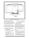
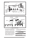
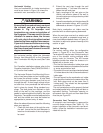
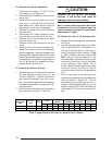
When the vent pipe must exit an exterior wall
close to the grade or expected snow level, a
riser should be provided as shown in Figure 18.
Insulation is required to prevent freezing of this
section of pipe.
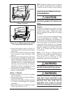
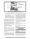
Vertical Venting
For vertical venting, either the configuration
shown in Figure 20 or the Concentric Vent
Termination Kit may be used. Vertical venting is
one of the shortest routing methods when
piping vents for furnaces. The M3 furnace
operates trouble-free when the furnace is in-
stalled with a shorter vent.
• The inlet for the combustion intake pipe must
be extended at least one foot above the roofline
or snow accumulation level.
• The outlet of the vent must be extended at least
10 inches above the inlet of the combustion air
intake pipe.
• The vent as well as the combustion air intake
pipe should be located on the same side of the
roof. Both pipes must not be closer than 5
inches apart. They should not be separated
more than 36 inches.
The roof penetration must be properly flashed
and waterproofed with a plumbing roof boot or
equivalent flashing. Termination spacing re-
quirements from the roof and from each other
must be per Figure 20.
Concentric Vent Termination
A concentric vent termination is approved for
use with these furnaces (See Table 12). For
proper installation of the concentric vent termi-
nation, follow the installation instructions pro-
vided with the kit.