


17
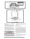
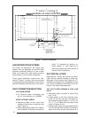
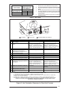
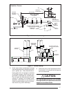
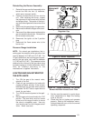
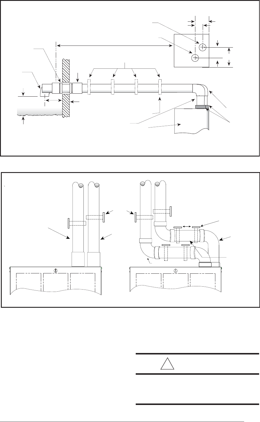
Figure 16. Horizontal Venting
Downflow Furnace
Seal/Caulk
Around Pipe
at Building
90˚ Elbow
12"
Min.
Normal Snow Level
Wall
Coupling
First Support Should be as Close to
Furnace Connection as Possible
Combustion Air
Intake Pipe
Furnace
3" x 2"
Reducer
Exhaust
Vent
PVC or
ABS pipe
Offset with
Vent for Adequate
Dimensional Clearance
3 1/2"
See Vent Table 4
Straps or Other Suitable
Supports at Minimum of
5 ft. Intervals
Upward Pitch - 1/4" Per Foot
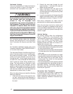
Outlet Exhaust Vent
Top View
6"
3 9/16"
1 7/8"
Vent
Combustion
Air Intake Pipe
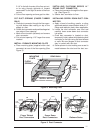
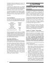
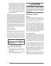
Figure 17. Vertical Venting
Upward Pitch
1/4" per foot
Vent
First support should be as
close to furnace as possible
Combustion Air Intake
Pipe
5'
Combustion Air
Intake Pipe
Vent
Support System
on Vertical Rise
Below Joints
5. Avoid areas where condensate drainage
may cause problems by dropping on plant-
ers or patios, etc. Also ensure that ex-
haust gases will not impinge on windows
or building surfaces, which may be com-
promised or damaged by condensation.
Do not install the vent terminal such that
exhaust is directed into window wells,
stairwells, under decks or into alcoves or
similar recessed areas, and do not termi-
nate above any public walkways.
6. Select the point of wall penetration where
the minimum 1/4 inch per foot of slope up
can be maintained.
!
CAUTION:
For optimal performance vent furnace
through wall which experiences the least
exposure to winter winds.