


30
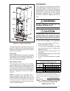
!
WARNING:
Never operate the furnace without a
filter in place. Dust and lint in the return
air can build up on internal compo-
nents, resulting in loss of efficiency,
equipment damage, and possible fire.
Lubrication
The bearings in the circulating air blower mo-
tors are pre-lubricated and sealed at the fac-
tory. No further oiling of the bearings is required
for the life of the motor.
Condensate Drain Assembly
Be sure the condensate lines are free and open
(i.e. avoid kinking hoses). Also make sure all
hose clamps are tight to avoid drawing air into
the system.
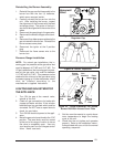
Blower Compartment
The blower compartment should be cleaned
monthly during the heating and cooling sea-
sons to remove any dirt and lint that may have
accumulated in the compartment or on the
blower and motor. Dirt and lint can create
excessive loads on the motor resulting in higher
than normal operating temperatures and short-
ened service life.
Heat Exchanger and Burner Maintenance
The furnace should operate for many years
without excessive soot buildup in the flue pas-
sageways, however, the flue passageways,
the vent system, and the burners should be
inspected and cleaned (if required) by a quali-
fied service technician annually to ensure con-
tinued safe operation. Particular attention must
be given to identify deterioration from corrosion
or other sources.
SYSTEM OPERATION
INFORMATION
GENERAL
Proper maintenance is most important to
achieve the best performance from a
furnace. Follow these instructions for years
of safe, trouble free operation.
• Do not place combustible materials on or
against the furnace cabinet or the vent pipe.
• Do not store gasoline or any other
flammable vapors and liquids in the vicinity
of the furnace.
• Change or replace the air filters monthly
during any period when the circulating
blower is operating regularly.
• Always replace the doors on the furnace
after servicing. Do not operate the furnace
without all doors and covers in place.
• Avoid operating the furnace when windows
and doors are open.
• Be sure that the thermostat is properly
installed and is not being affected by
drafts or heat from lamps or other
appliances.
Sequence of Operation
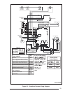
Operating sequences for the heating, cooling,
and fan modes are described below. Refer to
the wiring diagrams (Figures 30) and the low
voltage field wiring diagram (Figure 26) for
more details.
Heating Mode:
1. On a call for heat the thermostat closes,
applying 24 VAC to the W terminal on the
control board.
2. The control board checks for continuity
on the 24 VAC limit control circuit (over-
temperature limit switch, flame rollout
switches and blocked vent switch in se-
ries). If an open limit is detected the con-
trol board will energize the inducer and
the conditioned air blower. All other sys-
tem functions will be inoperable until the
limit circuit closes. While the limit is open,
the red LED will pulse at a rate of 1 blink
per unit time.
3. The furnace control checks for continuity
across the pressure switch (24 VAC). If
the pressure switch is closed the heat
mode sequence will not continue. If it
remains closed for 10 seconds the red
LED will blink 3 times repetitively until the
fault condition clears.
4. The inducer is energized.
5. The pressure switch will close. If the
pressure switch does not close after 10
seconds the fault LED will blink 2 times
repetitively and the inducer will continue
to run until the switch is closed.
6. The inducer will pre-purge for 30 seconds
and then the igniter will start its warm-up
as follows: