


10
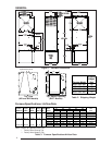
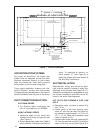
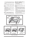
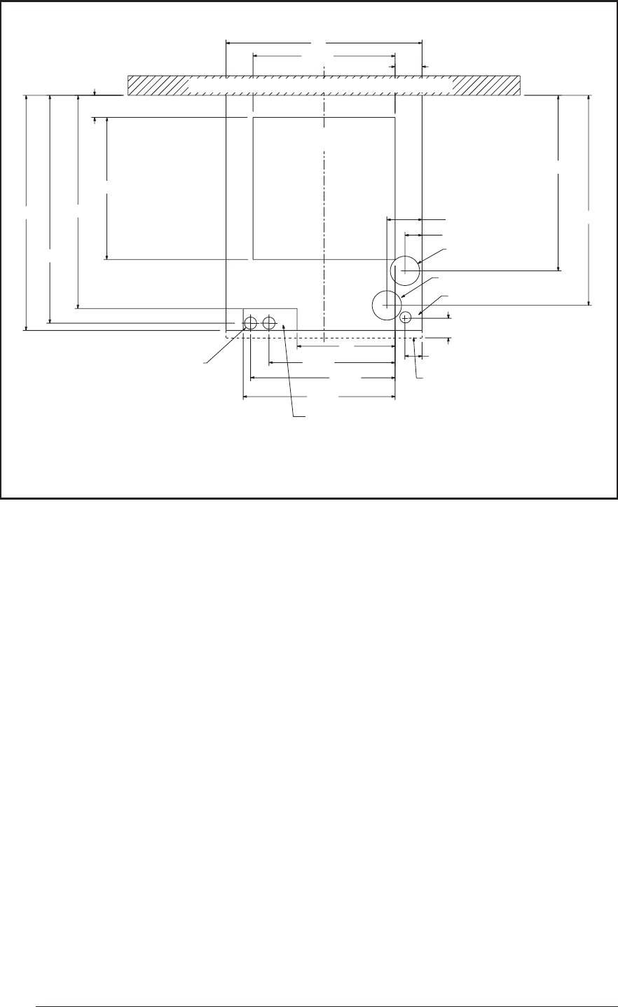
Figure 7. Cut-Out Locations
2-3/4
2
1-3/4
17-29/32
21-7/16
1-3/4
3-19/32
14-1/2
14-1/2
2-1/4
23-1/4
12-7/8
14-3/4
20
24
21-3/4
10
15-1/2
˚
ALT FUEL LINE
ENTRY
1-1/4
VENT
FUEL LINE ENTRY
FURNACE
OUTER DOOR
FLOOR CUT-OUT
FOR DUCT CONNECTIONS
FLOOR CUT-OUT
FOR OPTIONAL
COOLING COIL
FOR NON-PLATINUM
SERIES UNITS
FURNACE OUTLINE
REAR WALL OF CLOSET OR ALCOVE
COMBUSTION AIR INTAKE
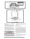
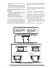
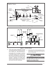
AIR DISTRIBUTION SYSTEMS
For proper air distribution, the supply duct
system must be designed so that the static
pressure measured external to the furnace
does not exceed the listed static pressure
rating shown on the furnace rating plate.
Three typical distribution systems are illus-
trated in Figure 2. Location, size, and number
of registers should be selected on the basis of
best air distribution and floor plan of the home.
DUCT CONNECTOR SELECTION
PLATINUM SERIES
a. For Platinum ready construction use
the 14” round plenum, p/n: 903896.
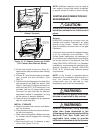
NON-PLATINUM SERIES
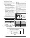
a. Determine depth of floor cavity from
surface of floor to top of supply air duct
(See Figure 3).
b. Select appropriate model from Table 5
which matches X-dimension of the floor
cavity. To maximize air delivery, re-
move reducer “C” (see Figure 5) to
obtain the largest open area that will fit
the duct/floor construction.
DUCT INSTALLATION
Required floor, ceiling, and roof cut-out open-
ings must be carefully located to avoid mis-
alignment of the furnace (see Figures 6 & 7).
Installation procedures are suggested for typi-
cal furnace installations and need not be fol-
lowed in the exact listed sequence.
CUT OUT FLOOR OPENING & FUEL LINE
HOLE
a. Determine center of closet or alcove (Fig-
ures 7 & 8).
b. Locate center of the floor opening, mea-
sured 10" from the rear wall, and mark cut-
out measuring approximately 14-1/2" by 14-
1/2" (± 1”) for model duct connector used
(refer to Figures 4 & 5).
c. Locate center of gas line hole, measured 23-
1/4" from the rear wall and 6-5/8" to the left of
center of the floor cut-out (See Figure 6) or