


23
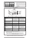
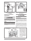
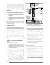
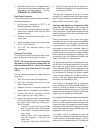
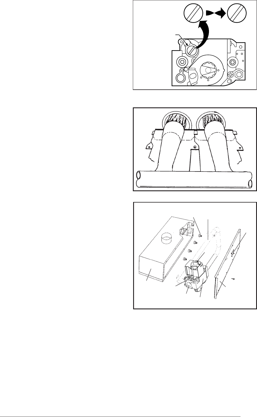
Figure 25. Typical Installation For Sealed
Burner Box With Access Cover Plate
Burner
Orifices
Gas
Manifold
Flame
Observation
Port
Gas
Valve
Access
Cover
Plate
Burner
Box
Inlet
Pressure
Tap
Inlet
On/Off
Lever
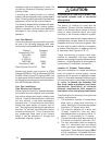
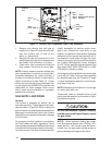
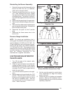
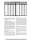
Figure 24. Burner Inspection
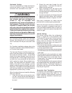
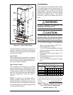
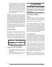
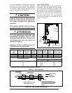
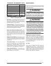
Figure 23. Convertible Pressure
Regulator Cap
Honeywell
Valve
PRESSURE
REGULATOR
CAP
M11678
N
A
T
N
A
T
L
P
L
P
N
A
T
N
A
T
OR
OTHER SIDE
OF CAP
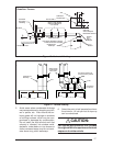
Reinstalling the Burner Assembly:
1. Reinstall the gas manifold assembly to the
burner box with the four (4) fasteners,
which were removed earlier.
2. Carefully reinstall the burner box into the
unit. After installing the burner, inspect
the alignment of the burners with the heat
exchanger tubes. The center of the burn-
ers should be aligned with the center of the
tubes.
3. Reconnect the gas piping to the gas valve.
4. Reconnect the wires to the gas valve termi-
nals.
5. Reconnect the rubber pressure tubes to the
gas valve and the burner box. Reinstall the
burner access cover plate.
6. Reconnect the ignitor at the 2 position
plug.
7. Reconnect the flame sensor wire to the
burner box.
Pressure Gauge Installation
NOTE: For natural gas installations, the in-
coming gas line pressure at the gas valve inlet
must be between 4.5” WC and 10.0” WC. For
LP gas installations, the incoming gas line pres-
sure at the gas valve inlet must be between
11.0” WC and 14.0” WC. This pressure can be
checked at the inlet end of the gas valve using
a pressure gauge or U-tube manometer, which
must be installed according to the
manufacturer’s supplied instructions.
LIGHTING AND ADJUSTMENT OF
THE APPLIANCE
1. Turn ON the gas at the manual valve,
outside of the unit.
2. Check all gas connections for leaks with
a soap and water solution. If the solution
bubbles there is a gas leak which must be
corrected. Do NOT use an open flame to
check for gas leaks.
3. Turn ON the electrical power to the appli-
ance.
4. Move the gas valve lever/knob to the “ON”
position. The lever/knob must be moved
to the end of its range of motion to insure
the valve is completely open. Use only
your hand to push in or turn the gas control
valve. Never use tools.
5. Set the room thermostat to a point above
room temperature to begin the heating
cycle of the unit.
6. Check that the unit ignites and operates
properly. Refer to the installation instruc-
tions provided with your unit for the normal
operating sequence.