


26
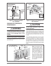
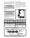
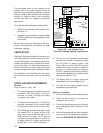
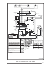
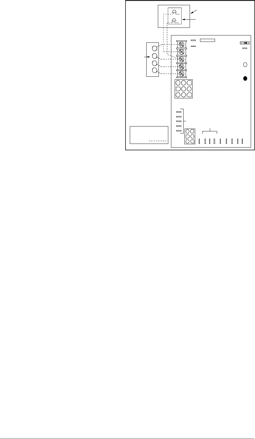
Figure 28. Low Voltage Field,
Four-wire Heating/Cooling Applications
R C Y G W
A/C Condensing Unit
Condensing Unit
Control Box
Room
Thermostat
Flame Signal Light
(Yellow)
Status Light
(Red)
60
90
120
180
Blower Off
Timing
TWIN
3 Amp
Fuse
COM
24 V
HUM
Neutrals
Low Voltage
Connections
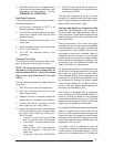
41
52
63
7
8
9
4
5
6
1
2
3
EAC
HUM
M1
M2
M3
COOL
HEAT
L1
XFMR
Unused Motor Leads
EAC
R Y G W
Connect
R & W
For
Heating
Only
FIELD WIRING
NOTE: The "Y"
terminal on the
UTEC control board
must be connected
to the thermostat
for proper cooling
mode operation.
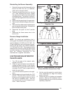
The thermostat must not be installed on an
outside wall or any other location where its
operation may be adversely affected. Adverse
affects include radiant loading from fireplaces,
sunlight, or lighting fixtures, and convective
loading from warm air registers or electrical
appliances.
To check the heat anticipator setting either:
1. Add the current draw of the system com-
ponents; or
2. Measure the current flow on the thermostat
R-W circuit after the circulating blower motor
has started.
Set the heat anticipator according to the ther-
mostat manufacturer's instructions for heat
anticipator settings.
VENTILATION
Ventilation must be provided for homes built to
HUD Manufactured Homes Safety and Con-
struction Standards. This ventilation can be sup-
plied by the VentilAire III or VentilAire IV acces-
sories. (See Table 12). Alternate means to pro-
vide the ventilation air must meet the require-
ments of all applicable local and federal codes.
For installation of the VentilAire III or IV, follow
the instructions provided with the VentilAire
kit.
START-UP AND ADJUSTMENTS
General
Prior to start-up, verify that:
1. The line voltage power leads are securely
connected, that the polarity of the con-
nections is correct, and that the furnace
is properly grounded.
2. The thermostat wires (R, W, Y, and G) are
securely connected to the correct leads
on the terminal strip of the circuit board.
3. The natural gas line service pressure must
not exceed 10.0 in. water column (0.36
psig), and must not be less than 4.5 in.
water column (0.16 psig). For LP gas the
line service pressure must not exceed 14
in. water column (0.51 psig), and must not
be less than 11.0 in. W.C. (0.40 psig).
4. The roll-out and vent safety manual reset
switches are closed. If necessary, press
the red button to reset a switch. See
Figure 26 for location. DO NOT install a
jumper wire across a switch to defeat its
function. If a switch reopens on start-up,
DO NOT reset the switch without identify-
ing and correcting the fault condition which
caused the switch to trip.
5. The blower door is in place, closing the
door switch in the line voltage circuit.
6. The gas line has been purged and all
connections are leak tight.
Start-Up Procedure
1. Set the thermostat to the lowest setting.
2. Close the disconnect(s) to provide line
voltage to the furnace.
3. Follow the procedures given on the oper-
ating instructions label attached to the
furnace.
4. Set the thermostat above room tempera-
ture and verify the sequence of operation.
(See the SEQUENCE OF OPERATION.)