


15
*NOTES
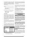
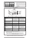
1. Subtract 3.5 ft. for each additional 3" 90 degree elbow.
2. Two 45 degree elbows are equivalent to one 90 degree elbow.
3. One short radius elbow is equivalent to two long radius
elbows.
4. Do not include termination elbows in calculation of vent length.
5. This table is applicable for elevations from sea level to 4000
ft. For higher elevations, decrease vent pipe lengths by 8% per
1000 ft. of altitude.
6. Only the above pipe materials are approved for use with these
condensing furnaces.
PVC,CPVC or ABS
Inlet/Outlet
SCH. 40 Pipe Size 3" 3"
Model M3RL 060
50 50
Model M3RL 080
50 50
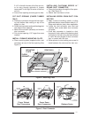
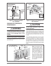
APPLICATION
MAXIMUM
DIRECT VENT, DUAL
PIPE LENGTH (ft.)*
Table 6. Vent Table
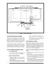
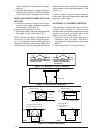
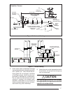
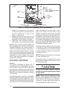
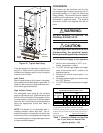
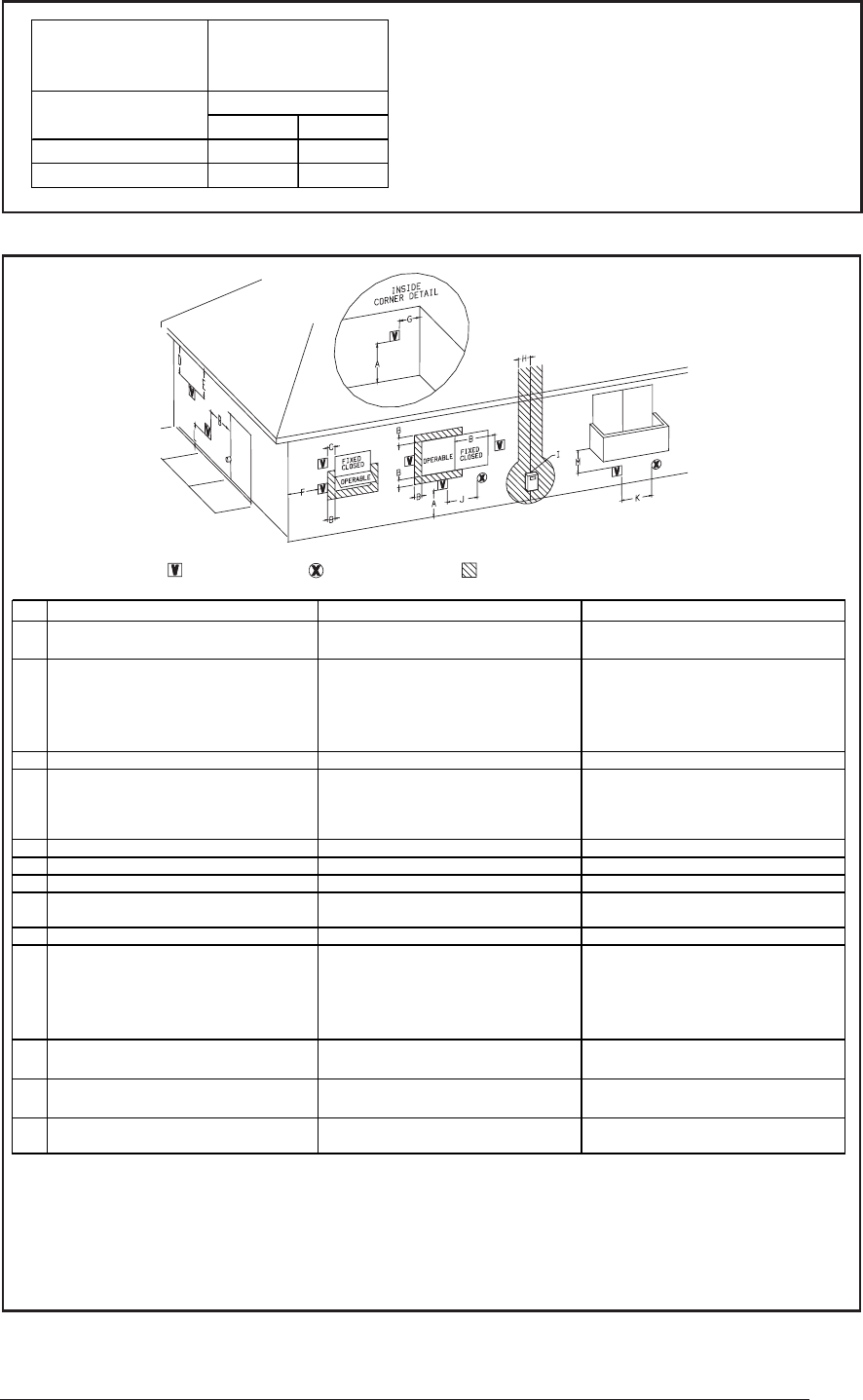
VENT TERMINAL
AIR SUPPLY INLET
AREA WHERE TERMINAL IS NOT PERMITTED
1
In accordance with the current CSA B149.1
Natural Gas and Propane Installation Code
2
In accordance with the current ANSI Z223.1 / NFPA 54
National Fuel Gas Code
† A vent shall not terminate directly above a sidewalk or paved driveway that is located between two single family
dwellings and serves both dwellings.
‡ Permitted only if veranda, porch, deck, or balcony is fully open on a minimum of two sides beneath the floor.
* For clearances not specified in ANSI Z223.1 / NFPA 54 or CSA B149.1, the following statement shall be included:
“Clearance in accordance with local installation codes, and the requirements of the gas supplier and the
manufacturer’s installation instructions.”
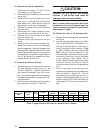
Canadian Installations
1
US Installations
2
A =
Clearance above grade, veranda, porch,
deck, or balcony
12 inches (30 cm) 12 inches (30 cm)
B =
Clearance to window or door that may be
opened
6 inches (15 cm) for appliances
≤
10,000
Btuh (3 kW), 12 inches (30 cm) for
appliances > 10,000 Btuh (3 kW) and
≤
100,00 Btuh (30 kW), 36 inches (91 cm) for
appliances >100,00 Btuh (30 kW)
6 inches (15 cm) for appliances
≤
10,000
Btuh (3 kW), 9 inches (23 cm) for
appliances > 10,000 Btuh (3 kW) and
≤
50,000 Btuh (15 kW), 12 inches (30 cm) for
appliances > 50,000 Btuh (15 kW)
C =
Clearance to permanentl
y
closed window
**
D =
Vertical clearance to ventilated soffit
located above the terminal within a
horizontal distance of 2 feet (61 cm) from
the center line of the terminal
**
E =
Clearance to unventilated soffit
**
F =
Clearance to outside corner
**
G =
Clearance to inside corner
**
H =
Clearance to each side of center line
extended above meter/re
g
ulator assembl
y
3 feet (91 cm) within a height 15 feet
above the meter/re
g
ulator assembl
y
*
I =
Clearance to service regulator vent outlet 3 feet (1.83 m)
*
J =
Clearance to nonmechanical air supply inlet
to building or the combustion air inlet to any
other appliance
6 inches (15 cm) for appliances
≤
10,000
Btuh (3 kW), 12 inches (30 cm) for
appliances > 10,000 Btuh (3 kW) and
≤
100,00 Btuh (30 kW), 36 inches (91 cm) for
appliances >100,00 Btuh (30 kW)
6 inches (15 cm) for appliances
≤
10,000
Btuh (3 kW), 9 inches (23 cm) for
appliances > 10,000 Btuh (3 kW) and
≤
50,000 Btuh (15 kW), 12 inches (30 cm) for
appliances > 50,000 Btuh (15 kW)
K =
Clearance to a mechanical air supply inlet 6 feet (1.83 m) 3 feet (91 cm) above if within 10 feet (3 m)
horizontally
L =
Clearance above paved sidewalk or paved
driveway located on public property
7 feet (2.13 m) †
*
M =
Clearance under veranda, porch deck, or
balcony
12 inches (30 cm) ‡
*
Figure 15. Vent Termination Clearances for Direct Vent Furnaces