


22
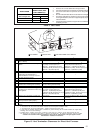
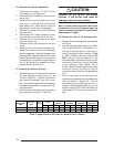
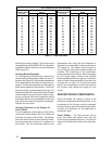
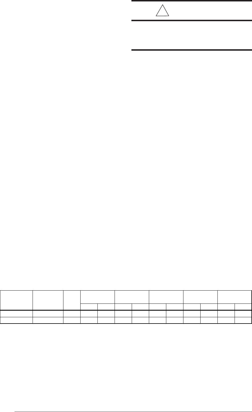
Table 8. Approximate Orifice Size for Natural and LP Gases
Nat LP Nat LP Nat LP Nat LP Nat LP
060A-A/BW 60,000 4 50 57 50 57 51 58 51 58 52 59
080A-A/BW 80,000 5 49 1.15 mm 49 1.15 mm 50 57 50 57 51 58
Furnace
Model Number
M3RL -
Furnace Rating
Plate Input
(Btuh)
No. of
Burners
Elevation
0 - 2000
Elevation
2000-4000
Elevation
4000-6000
Elevation
6000-8000
Elevation
8000-10000
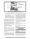
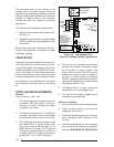
To Remove the Burner Assembly:
1. Follow the instructions “To Turn Off the
Fuel Supply to the Appliance.”
2. Disconnect the flame sensor wire from the
burner box.
3. Disconnect the ignitor wires at the 2 pin
plug. This is a locking quick connect and
both sides of the lower section must be
depressed in order to be separated.
4. Remove the wires from the terminals of
the gas valve.
5. Disconnect the rubber pressure tubes
from the gas valve and the burner box.
6. Remove the burner access cover plate
from the burner box.
7. Remove supply gas piping from the gas
valve.
8. Carefully remove the burner assembly fas-
teners and remove the burner assembly
from the appliance. Keep the fasteners that
were removed. Note that the burner box may
have hooks near the top and on the right and
left hand sides. To remove this type of burner
box, lift the burner box upwards and then
remove the box from the unit.
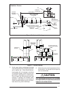
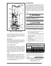
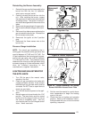
To Remove the Burner Orifices:
1. Remove the four (4) fasteners that secure
the gas manifold to the burner box, as
shown in Figure 25. Carefully remove the
gas manifold assembly from the burner
box. Note that the gas manifold assembly
consists of the gas valve, the gas manifold,
and the orifices.
2. Carefully remove the burner orifices from the
gas manifold, as shown in Figure 25.
!
CAUTION:
Caution: Do not re-drill the burner
orifices. If the orifice size must be
changed, use only new orifices.
Note: The size of the new orifices that will be
installed into the unit will depend upon the
type of conversion (sea level or high altitude;
natural gas or LP gas).
To Convert the Unit to the Alternate Gas
1. Remove the orifice bag from the manifold
of the unit.
2. Install the appropriate gas burner orifices
into the gas manifold. Remember if in-
stalling at altitudes above 4,000 feet to
install the proper orifices, shown in Table
8. When installing the new orifices, DO
NOT use pipe joint compound on the
orifice threads. Screw the orifices into the
manifold by hand until snug to eliminate
cross threading, then tighten with a
wrench. Before installing an orifice, check
the face or side of the orifice for the drill
number to ensure that it is the appropriate
size.
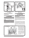
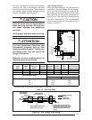
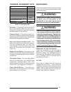
3. For the conversion to the alternate fuel,
the gas valve regulator cap must be turned
over, as shown in Figure 23. You will
unscrew the cap and reinstall for your in-
stallation. After reinstalling the cap, you will
be able to read "NAT" for the conversion to
natural gas or "LP for the conversion to LP
gas.