


24
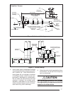
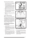
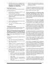
7. After the flame ignites, visually inspect the
burner assembly to ensure that the flame
is drawn directly into the center of the heat
exchanger tube, as shown in Figure 23.
The end of the flame will be out of sight
around the bend of the heat exchanger
tube. In a properly adjusted burner assem-
bly, the flame color should be blue with
some light yellow streaks near the outer
portions of the flame.
NOTE: Until all of the air is bled out of the gas
line, the hot surface ignitor may not ignite the gas.
If the ignition control locks out, turn the thermostat
to its lowest setting and wait one minute then turn
the thermostat to a point above room temperature
and the ignitor will try again to ignite the main
burners. This process may have to be repeated
several times before the burners will ignite. Once
the burners are lit, check all gas connections for
leaks again with the soap and water solution. If
the solution bubbles there is a gas leak which
must be corrected. Do not use an open flame to
check for gas leaks.
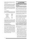
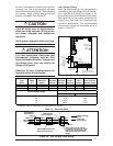
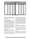
Manifold Pressure
The gas valve for the M3 furnace series is
equipped with a special conversion pres-
sure regulator cap. The pressure regulator
cap is factory set. If the gas valve is con-
verted from natural gas to propane gas or
vise versa, the manifold pressure of the gas
valve will be set to pressure listed in Table 9.
COMPLETING THE CONVERSION
1. Affix the gas valve conversion label found
in the package with the orifices to the unit
rating plate.
2. Run the appliance through a complete
cycle to assure proper operation.
!
CAUTION:
To avoid electric shock, personal
injury, or death, turn off the power at
the disconnect or the main service
panel before making any electrical
connections.
ELECTRICAL WIRING
General
Electrical connections must be made in accor-
dance with all applicable local codes and ordi-
nances, and with the current revision of the
National Electric Code (ANSI/NFPA 70).
For Canadian installations electrical connec-
tions and grounding must be done in accor-
dance with the current Canadian Electrical
Code (CSA C22.1 Part 1) and/or local codes. If
any of the original wire as supplied with the
furnace must be replaced, it must be replaced
with wire having a minimum temperature rating
of 105°C. Refer to the furnace nameplate and
Table 8 for electrical requirements.
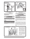
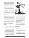
Line Voltage Wiring
The line voltage (115 volt) to the furnace must
be supplied from a dedicated branch circuit
containing the correct fuse or circuit breaker
for the furnace. See Table 10. An electrical
switch should be readily accessible from and
within sight of the furnace. See the Wiring
Diagram label in the furnace for more details.
The furnace cabinet must have an uninter-
rupted, unbroken ground to minimize injury
should an electrical fault condition occur. The
controls used in this furnace require an earth
ground to operate properly. Acceptable meth-
ods for grounding are electrical wire or conduit
approved for electrical ground service. Do not
use gas piping as an electrical ground.
NOTE: Proper line voltage polarity must be
maintained in order for the control system to
operate correctly. Verify that the incoming neu-
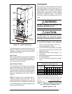
Table 9. Manifold Pressure
Type of Fuel Manifold Pressure
In. WC
Natural Gas: 3.5
Propane (LP) Gas: 10.0