


20
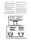
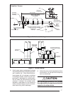
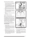
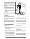
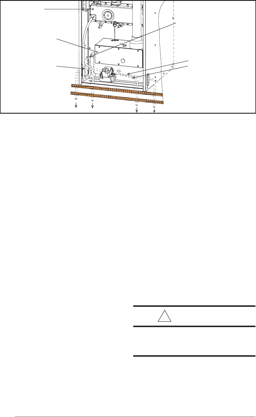
Figure 21. Furnace with Condensate Drain Trap Assembly
A
A
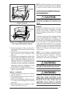
Clamp
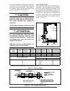
Step 1: Loosen
Step 2: Rotate to drain direction
Step 3: Retighten
Keep
Downward
Slope
Alt. Drain
Alt. Drain
Alt. Drain
Alt. Drain
Floor Cavity
Floor
“Hard”
J Drain Tube
Burner
Box
Collector
Box
1. Remove the collector box soft tube at
location A in Figure 21 and insure the exit
from the collector box is clear of any
debris or obstructions.
2. Replace this tube and insure the fit to the
header spout is air tight. Air will be drawn into
the header if this connection is not tight.
3. Check other tube connections along the
drain system. Insure that all are air tight.
NOTE: Industry research studies indicate that
when condensate is routed to an active drain,
household detergents, etc., buffer its acidity. If
the drain is not actively used or if codes require,
obtain a neutralizer kit (See Table 12). Proper
drains and connections to the condensate tub-
ing are required as NORDYNE cannot be held
responsible for water leakage which occurs
due to loose hose connections or improperly
sealed drain line pipes.
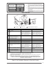
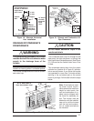
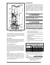
GAS SUPPLY AND PIPING
General
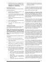
This furnace is equipped for bottom, left, or
right side gas entry. Typical gas service hook-
ups are shown in Figure 22. When making the
gas connection provide clearance between the
gas supply line and the entry hole in the furnace
casing to avoid unwanted noise and/or damage
to the furnace.
All gas piping must be installed in compliance
with local codes and utility regulations. Some
local regulations require the installation of a manual
main shut-off valve and ground joint union exter-
nal to the furnace. The shut-off valve should be
readily accessible for service and/or emer-
gency use. Consult the local utility or gas
supplier for additional requirements regarding
placement of the manual main gas shut-off. In
the absence of local codes, the gas line instal-
lation must comply with the provisions stated in
the Federal Manufactured Home Standard
(H.U.D Title 24, part 280) and the National Fuel
Gas Code (ANSI Z223.1/NFPA-54) or (CAN/
CGA B149) installation codes.
A drip leg should be installed in the vertical pipe
run to the unit. Table 7 lists gas flow capacities
for standard pipe sizes as a function of length
in typical applications based on nominal pres-
sure drop in the line.
NOTE: Gas piping must not be run in or through
air ducts, gas vents, etc.
Compounds used on threaded joints of gas
piping must be resistant to the actions of lique-
fied petroleum gases.
!
CAUTION:
Do not use matches, lighters, candles,
or other sources of open flame to check
for gas leaks.
NOTE: When pressure testing gas supply
lines at pressures greater than 1/2 psig (14 in.
water column), the furnace must be discon-
nected from the gas supply piping system to
prevent damage to the gas control valve.