


28
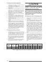
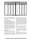
TIME FOR TIME FOR
ONE REVOLUTION ONE REVOLUTION
(SECONDS) 1 5 10 (SECONDS) 1 5 10
24 150 750 1500 80 45 225 450
26 138 692 1385 82 44 220 439
28 129 643 1286 84 43 214 429
30 120 600 1200 86 42 209 419
32 113 563 1125 88 41 205 409
34 106 529 1059 90 40 200 400
36 100 500 1000 92 39 196 391
38 95 474 947 94 38 191 383
40 90 450 900 96 38 188 375
42 86 429 857 98 37 184 367
44 82 409 818 100 36 180 360
46 78 391 783 102 35 176 353
48 75 375 750 104 35 173 346
50 72 360 720 106 34 170 340
52 69 346 692 108 33 167 333
54 67 333 667 110 33 164 327
56 64 321 643 112 32 161 321
58 62 310 621 114 32 158 316
60 60 300 600 116 31 155 310
62 58 290 581 118 31 153 305
64 56 281 563 120 30 150 300
GAS FLOW RATE (CUBIC FEET PER HOUR)
CUBIC FEET PER REVOLUTION OF
METER
CUBIC FEET PER REVOLUTION OF
METER
Table 11. Gas Flow Rate
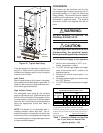
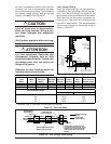
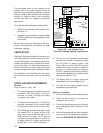
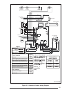
after the gas valve is closed. This timing can be
changed using the BLOWER OFF timing switch
opposite the terminal block on the control board
(See Figure 27).
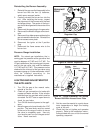
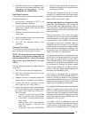
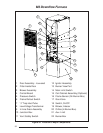
Verifying Burner Operation
To verify operation of the burners, remove front
door and ensure that the door switch is in the “on”
position (see Figure 29). Set the thermostat above
room temperature and observe the ignition se-
quence. The flame can be observed through the
small clear window on the burner box. The burner
flame should carry over between all burners. The
flames should be blue, without yellow tips. Flames
should extend from each burner without lifting,
curling, or floating. After verifying ignition, set the
thermostat below room temperature and verify
that the burner flame extinguishes completely.
Replace the front door.
Verifying Operation of the Supply Air
Limit Switch
To verify operation of the supply air limit switch,
make sure that the blower door is in place and
that there is power to the furnace. Completely
block the return airflow to the furnace by install-
ing a close-off plate in place of or upstream of
the filter(s). Set the thermostat above room
temperature and verify that the Sequence of
Operation is as described in these instructions.
The supply air limit switch should function to
turn off the gas valve within approximately five
minutes. The circulating air and combustion
blowers should continue to run when the supply
air limit switch opens. Remove the close-off
plate immediately after the supply air limit switch
opens. If the furnace operates for more than five
minutes with no return air, set the thermostat
below room temperature, shut off the power to
the furnace, and replace the supply air limit
switch.
DESCRIPTION OF COMPONENTS
Figure 29 shows the location of each of the
functional components described below. If any
component of the furnace must be replaced,
use only factory authorized replacement parts.
Contact your distributor for the approved re-
placement parts.
Flame Sensor – The flame sensor acts to
prove that flame has carried over from the
ignitor to the opposite end burner. If no flame is
sensed, the furnace will be shut down automati-
cally.