


16
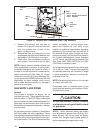
escape through such appliances or vents. Do
not vent the furnace to a fireplace chimney or
building chase.
If removing an existing furnace in a venting
system, the venting system may not be properly
sized. To test the vent system with the remaining
appliances, follow the test outlined below.
The following steps shall be followed with each
appliance connected to the venting system
placed in operation, while any other appliances
connected to the venting system are not in
operation:
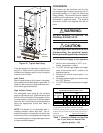
Vent Pipe Material
Vent and combustion air pipe and fittings must
be one of the following materials and must
conform to the indicated ANSI/ASTM standards:
Material Standard
Schedule 40 PVC D1785
PVC-DWV D2665
SDR-21 D2241
& SDR-26
ABS-DWV D2661
Schedule 40 ABS F628
Foam/Cellular Core PVC F891
Cement and primer must conform to ATSM
Standard D2564 for PVC and Standard D2235
for ABS. When joining PVC piping to ABS, use
an appropriate solvent cement and procedure
per the piping manufacturer's recommendation
and ASTM Standard D3138.
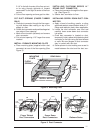
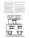
Vent Pipe Installation
Pipe Routing and Support
Route piping as directly as possible between
the furnace and the outdoors and remember
that routing affects pipe length limitations per
Table 6. Locate the combustion air intake and
the vent exhaust in the same atmospheric
pressure zone - i.e. both must exit the building
though the same portion of exterior wall or
roof. Vent piping must be sloped upwards not
less than 1/4" per foot in the direction from the
furnace to the terminal. This is to ensure that
any condensate flows back to the furnace
where it can be disposed of through the
condensate disposal system.
!
CAUTION:
Combustion air must not be drawn from
occupied spaces and a corrosive
atmosphere.
The quality of outdoor air must also be
considered. Be sure that the combustion air
intake is not located near a source of solvent
fumes or other chemicals which can cause
corrosion of the furnace combustion system.
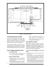
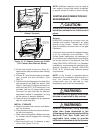
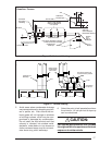
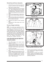
Piping must be mechanically supported so that
its weight does not bear down on the furnace.
Supports must be at intervals no greater than
five feet, and at smaller intervals if necessary
to ensure that there are no sagging sections
to trap water (See Figures 16 & 17).
These condensing furnaces have been
certified for installation with zero clearance
between vent piping and combustible surfaces.
However, it is good practice to allow space for
convenience in installation and service.
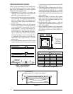
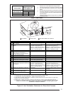
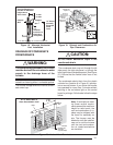
Location of Outdoor Terminations
Vent and combustion air intake terminations
must be located to ensure proper furnace
operation and to conform to applicable codes.
Figure 15 illustrates necessary distances from
the vent termination to windows and building
air intakes. In Canada, the Canadian Fuel
Gas Code takes precedence over these
instructions. Specifically, all minimum
distance requirements with respect to
termination of the vent piping listed below.
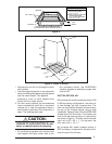
The following list is a summary of vent terminal
location requirements:
1. The termination must be 12 inches above
snow level or grade level whichever is
higher. See Figure 18 for alternate method
to achieve 12" above snow level.
2. The minimum distance for a direct vent
(2-pipe) installation from any door,
openable window, or air gravity inlet is 1 ft.
below, 1 ft. horizontally, or 1 ft. above.
3. The vent termination shall be a minimum of
3 ft. above any forced air inlet within 10 ft.
4. The vent termination shall be located at
least 4 ft. horizontally from any electric
meter, gas meter, regulator and any relief
equipment. These distances apply ONLY
to U.S. installations. In Canada, the Cana-
dian Fuel Gas Code takes precedence.