


27
5. After the furnace has run for approximately
five minutes, set the thermostat below room
temperature and verify steps 9 - 11 of the
SEQUENCE OF OPERATION.
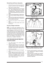
Shut Down Procedure
In the event that the furnace must be shut down,
follow this procedure:
1. Set the room thermostat to "OFF" or its
lowest temperature setting.
2. Turn OFF the main gas supply to the appli-
ance at the manual valve outside of the
appliance casing.
3. Remove the control access panel / lou-
vered door.
4. Move the appliance gas valve lever/knob
to the “OFF” position.
5. Turn OFF the electrical power to the
appliance.
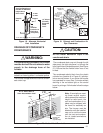
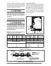
Verifying Firing Rate
The firing rate must be verified for each instal-
lation to prevent over-firing the furnace.
NOTE: The firing rate must not exceed the
rate shown on the furnace rating plate. At
altitudes above 4000 ft. it must not exceed
that on the rating plate less 4% for each
1000 ft.
Use the following procedure to determine the
firing rate:
1. Shut off all other gas fired appliances.
2. Start the furnace and allow it to run for at
least three minutes.
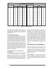
3. Measure the time (in seconds) required for
the gas meter to complete one revolution.
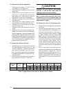
4. Convert the time per revolution to cubic
feet of gas per hour using Table 11.
5. Multiply the gas flow rate in cubic feet per
hour by the heating value of the gas in Btu
per cubic foot to obtain the firing rate in
Btuh. Example:
• Time for 1 revolution of a gas meter
with a 1 cubic foot dial = 60 seconds.
• From Table 11 read 60 cubic feet per
hour of gas.
• Heating value of the gas (obtained
from gas supplier) = 1000 Btu per
cubic foot.
• Firing rate = 1000 x 60 = 60,000 Btuh.
6. See the "High Altitude Derate" section for
additional information on firing rate at eleva-
tions above 4,000 ft.
The gas valve regulator is set at a nominal
value of 3.5 in. water column for use with natural
gas. The manifold pressure must be set at 10.0 in.
water column for use with LP gas.
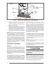
Verifying and Adjusting Temperature Rise
Verify that the temperature rise through the
furnace is within the range specified on the fur-
nace rating plate. Temperature rises outside the
specified range could result in premature heat
exchanger failure.
Place thermometers in the return and supply
air stream as close to the furnace as possible.
The thermometer on the supply air side must
be shielded from direct radiation from the heat
exchanger to avoid false readings. Adjust all
registers and duct dampers to the desired
position and run the furnace for fifteen minutes
before taking any temperature readings. The
temperature rise is the difference between the
supply and return air temperatures.
For typical duct systems, the temperature rise
will fall within the range specified on the rating
plate with the blower speed at the factory
recommended setting. If the temperature rise
measured is outside the range specified, it may
be necessary to change the blower speed.
Lower blower speeds will increase the tem-
perature rise and higher blower speeds will
decrease the temperature rise.
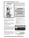
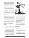
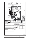
The furnace is equipped with a multispeed
motor. Heating and cooling speed selection is
made by moving the leads on the integrated
control board located in the furnace. The wiring
diagram on the furnace and Figure 30 show the
speed taps for adjusting motor speed.
If it is desired that the blower operate at the same
speed for heating and cooling, tape off the
terminal of the unused blower wire. Install the
jumper wire, found in the plastic instruction bag,
across the HEAT and COOL taps on the control
board. Reconnect the desired blower tap to the
piggyback quick connect.
The blower control is designed to start the
circulating air blower 30 seconds after the gas
valve is opened. The blower control is factory
wired to turn the blower motor off 120 seconds