


Revision 0.07
9
2 Installation & Connection
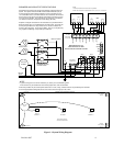
2.1 Mounting the DVP-120
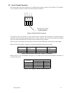
Mounting holes are provided in the DVP-120 case at the four corners. The top two are keyhole shaped so that
the panel can be hung and then the two bottom screws driven to hold the panel. Conduit entry holes are
provided on the top, bottom and right side of the panel. The panel should be mounted with sufficient space all
around, depending on the complexity of the installation.
Main power wiring should conform to national and local electrical codes, and may require separate inspections
and certification. Contact your local building authority for further details. If safety certification is required to
obtain your occupancy certificate, Macurco can contract to provide testing services to obtain certification (such
as the ETL label) by a national testing laboratory. Contact the Macurco Sales Department for further details.
2.2 General Wiring Information
WARNING
High voltage terminals (120/240 VAC) are located within the
DVP-120, presenting a hazard to service technicians. Only
qualified technicians should open the DVP-120 case and
service the internal circuits. Ensure power is removed from the
DVP-120 prior to servicing the unit.
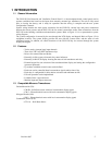
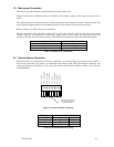
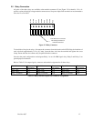
With the exception of the safety ground, all field wiring is done via modular connectors (provided) so that the
wiring can be done easily and then simply plugging the modular connectors into the matching connectors on the
PCB.
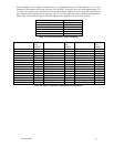
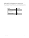
The power and signal connections to the remote mounted sensors should be size AWG18 (minimum) for short
runs. Refer to Table 2-2 for recommended wire gauges. Four conductor cables may be used in all cases since
the DVP-120 employs DC power for remote sensors to prevent electrical noise from interfering with the sensor
output signal.
Do not bundle sensor power and/or signal connections with other AC power cables to prevent electrical
interference. If other AC power connections must be bundled with the DVP-120 sensor cables, Macurco
recommends that the sensor connections be made with two twisted pairs of the appropriate gauge, with an
overall foil and braid shield. All shields should be terminated at the DVP-120 end of the cable only. A ground
stud is provided near the bottom left corner of the panel.
Typical part numbers for AWG18 are:
– Alphawire 55132
– Belden TBD