


Revision 0.07
11
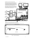
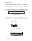
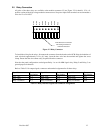
Each 8-terminal sensor modular connector may be disconnected from the PCB connector to ease wire
installation. The terminals will accept wire from 16 to 28 AWG. To install a wire, strip back approximately 0.25
in. (6 mm) of insulation, and insert the bare wire into the terminal. Tighten the screw clamp and ensure that the
wire cannot be easily pulled from the connector. Table 2-3 lists the connector to sensor channel correspondence.
While Table 2-4 lists channel signals, connector and terminal assignments for all 12 input channels.
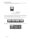
Control Board Connector Sensor Channels
J7 1, 2
J10 3, 4
J13 5, 6
J8 7, 8
J11 9, 10
J14 11, 12
Table 2-3 Connector to Sensor Channel Mapping
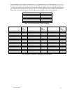
Signal Name Connector
-Pin
Number
Signal Name Connector
-Pin
Number
Signal Name Connector
-Pin
Number
CH 1 +24 Vdc J7-5 CH 5 +24 Vdc J13-5 CH 9 +24 Vdc J11-5
CH 1 +I loop J7-6 CH 5 +I loop J13-6 CH 9 +I loop J11-6
CH 1 -I loop J7-7 CH 5 -I loop J13-7 CH 9 -I loop J11-7
CH 1 24Vdc Ret J7-8 CH 5 24Vdc Ret J13-8 CH 9 24Vdc Ret J11-8
CH 2 +24 Vdc J7-1 CH 6 +24 Vdc J13-1 CH 10 +24 Vdc J11-1
CH 2 +I loop J7-2 CH 6 +I loop J13-2 CH 10 +I loop J11-2
CH 2 -I loop J7-3 CH 6 -I loop J13-3 CH 10 -I loop J11-3
CH 2 24Vdc Ret J7-4 CH 6 24Vdc Ret J13-4 CH 10 24Vdc Ret J11-4
CH 3 +24 Vdc J10-5 CH 7 +24 Vdc J8-5 CH 11 +24 Vdc J14-5
CH 3 +I loop J10-6 CH 7 +I loop J8-6 CH 11 +I loop J14-6
CH 3 -I loop J10-7 CH 7 -I loop J8-7 CH 11 -I loop J14-7
CH 3 24Vdc Ret J10-8 CH 7 24Vdc Ret J8-8 CH 11 24Vdc Ret J14-8
CH 4 +24 Vdc J10-1 CH 8 +24 Vdc J8-1 CH 12 +24 Vdc J14-1
CH 4 +I loop J10-2 CH 8 +I loop J8-2 CH 12 +I loop J14-2
CH 4 -I loop J10-3 CH 8 -I loop J8-3 CH 12 -I loop J14-3
CH 4 24Vdc Ret J10-4 CH 8 24Vdc Ret J8-4 CH 12 24Vdc Ret J14-4
Table 2-4 Sensor Connectors: Channel and Pin Assignments