


Revision 0.07
37
4.3 No Power
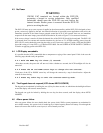
WARNING
120/240 VAC terminals are located within the DVP-120,
presenting a hazard to service technicians. Only qualified
technicians should open the DVP-120 case and service the
internal circuits. Ensure power is removed from the DVP-120
prior to servicing the unit.
The DVP-120 starts up as soon as power is applied to the microcontroller, and the DVP-120 is designed to have
power continuously applied to the unit. An external indication of successful power application to the unit is the
immediate operation of the Status Lamps grouped around the LCD. If the operator does not see immediate
response from the status lamps, power should be checked at J4 (refer to Figure 1-2 for connector locations).
If the correct voltage is noted at J4, then the internal fuse of the DVP-120 should be investigated. The DVP-120
is protected from over-current and transient situations by the fuse at F3. AFTER removing power from the
DVP-120, F3 can be checked by removing the safety cover. If necessary, replace F3 with a 5x20 mm SLO-BLO
fuse with a rating of 1 Amp 250V, e.g. Littlefuse P/N 218001. Be sure to REPLACE THE SAFETY COVER on
F3 before re-applying power to the DVP-120.
4.4 LCD Display unreadable
It is possible that the LCD is unreadable due to temperature or aging of the control panel. If this is the case the
following steps should rectify the problem:
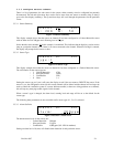
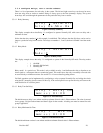
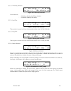
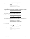
4.4.1 Hold the MENU key for three (3) seconds.
After three seconds, the power led will turn red. After a further two seconds, the LCD backlight will also be
turned off.
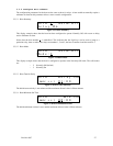
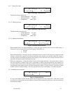
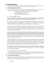
4.4.2 Press the UP and DOWN cursor keys to change the LCD contrast.
Each press of the UP or DOWN cursor key will change the contrast by a step in that direction. Adjust the
contrast for best viewing.
4.4.3 Press any other key to exit the contrast-setting mode.
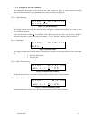
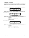
4.5 The Keypad does not respond (LCD shows KEYS LOCKED)
The keypad can be unlocked by holding the zero (0) key for three seconds. At which time the backlight will turn
on and the display will return to normal mode..
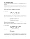
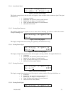
The keypad can again be locked by holding the zero key for three seconds, until the display shows KEYS
LOCKED.
4.6 After a power failure
After any power failure, the user should check the system clock. While system parameters are maintained in
non-volatile memory, the system clock is backed-up by a limited-capacity button cell battery. Even though the
button cell can run the clock for several years, it will eventually wear out.