


Revision 0.07
33
3.3.8.4 Alarm Strobe Signal
A
l
a
r
m
S
i
g
n
a
l
s
S
t
r
o
b
e
:
1
C
o
n
t
i
n
.
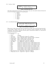
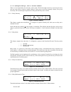
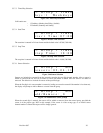
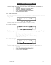
Figure 3-55 Strobe Alarm Signal
This display example shows that the strobe will signal an alarm condition with a continuous signal. The signal
definitions are:
– 1 Continuous (default)
– 2 Intermittent, one second on at two second intervals
– 3 Double Tap, two beeps at 5 second intervals
– 4 Triple Tap, three short beeps at 15 second intervals
– 5 Off, strobe will not flash
3.3.8.5 Warning Signal Summary
The warning signals are in response to one or more sensors indicating gas levels at or above the sensors’
configured warning level.
W
a
r
n
i
n
g
S
i
g
n
a
l
s
B
u
z
z
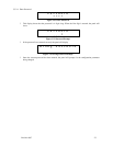
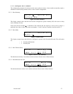
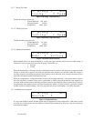
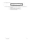
Figure 3-56 Warning Signals
This display example shows that warnings are signaled by the internal Buzzer only.
3.3.8.6 Warning Buzzer Signal
W
a
r
n
i
n
g
S
i
g
n
a
l
s
B
u
z
z
:
5
O
F
F
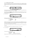
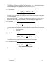
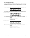
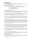
Figure 3-57 Buzzer Warning Signal
This display example shows that the buzzer will not signal a warning condition. The signal definitions are:
– 1 Continuous
– 2 Intermittent, one second on at two second intervals
– 3 Double Tap, two beeps at 5 second intervals
– 4 Triple Tap, three short beeps at 15 second intervals
– 5 Off, buzzer will not sound (default)
3.3.8.7 Warning Horn Signal
W
a
r
n
i
n
g
S
i
g
n
a
l
s
H
o
r
n
:
5
O
F
F
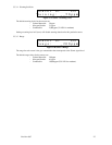
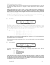
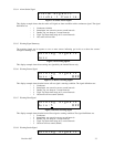
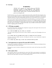
Figure 3-58 Horn Warning Signal
This display example shows that the horn will not signal a warning condition. The signal definitions are:
– 1 Continuous
– 2 Intermittent, one second on at two second intervals
– 3 Double Tap, two beeps at 5 second intervals
– 4 Triple Tap, three short beeps at 15 second intervals
– 5 Off, horn will not sound (default)
3.3.8.8 Warning Strobe Signal
W
a
r
n
i
n
g
S
i
g
n
a
l
s