


Revision 0.07
36
4 Troubleshooting
The DVP-120 is extensively tested at the factory to ensure reliable operation. Most problems can be traced to
the set-up of configurable features and modes, system wiring or trouble with the sensors.
4.1 System Status Light Flashing
The system status light (section 3.1.1) is normally green indicating power is present, but will change to yellow
whenever the controlling firmware detects a trouble condition. Possible trouble conditions are
– Any configured channel has less than 4 mA flowing in the current loop
– A sensor is reporting a trouble condition
– Any configured channel wiring is open.
– Internal controller board problems are detected.
4.1.1 Input Channel Trouble
Any time the POWER light is yellow, the first thing the technician should consider is that one of the input
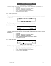
channels is in trouble. Reviewing the Sensor Status displays (using the up and down keys), should reveal which
channel has a problem since the gas reading will be replaced with the word TROUBLE.
A common source of trouble is an input channel that is configured for a sensor that does not exist. In this case,
the system expects to see current flowing within the current loop, but there cannot be current if there is no
sensor connected. Either fix the miss-wired sensor, or change the sensor type to NONE, section 3.3.3.2. After
returning to normal mode (using the MENU key), the power light should return to steady green.
If all channels are configured properly, another source of trouble could be the type of sensor attached to an input
channel. Macurco Toxic sensors can indicated high gas concentrations with signals of up to 24 mA in the
current loop. However, the combustible sensor (GT-11A) can indicate trouble with a 21 mA signal. Therefore, a
Toxic sensor connected to channel which is configured for a combustible sensor can cause a fault indication if
the gas concentration is high enough.
All Macurco sensors are either supplied with a STATUS lamp that will indicate the health of the device, or will
display a trouble message on the digital display. Macurco sensors may be tested by depressing the TEST button
on the sensor printed circuit board, or (depending on the type of sensor), the button on the interior front panel of
the unit. Macurco sensors will step the output current level from 4 mA to 20 mA over the course of the warm-up
period, allowing the technician to determine where the trouble exists. If the sensor is still in trouble, resetting
the power may clear the trouble. Remove one of the power wires from the sensor terminal strip causing the
sensor to go through a power-up reboot.
Finally, the wiring between the DVP-120 and the sensor should be investigated. The power input to the sensor
should be investigated at the sensor. Since Macurco sensors are rated for operation between 12 and 24 VDC or
VAC, the voltage drop between the DVP-120 and the sensor should not be an issue if the wiring guidelines in
Table 2-2 are followed. A multimeter can be inserted to check the current flow within the loop, or a continuity
test can be performed on all four wires between the DVP-120 and the sensor. Ensure power is removed from the
DVP-120 prior to removing the input or output connectors from the DVP-120 controller board.
Each sensor channel is provided with a PTC-resettable fuse internal to the DVP-120 to protect against over
current situations. To reset a sensor channel, power should be removed from the channel. This can be
accomplished by removing power from the sensor – causing the loop current to go to zero, or by completely
removing power from the DVP-120.
4.1.2 Internal Controller Board Trouble
If the sensor status display and investigative efforts reveal no problems with the input channel current loops and
channel configuration, the most likely trouble is an internal problem detected by the DVP-120 controller. In this
case, contact the Macurco Technical Department for advice and help.
4.2 Timed ventilation problem
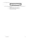
When using the timed ventilation mode the system clock should be checked regularly (at least twice a year).
The battery backed real time clock in the DVP-120 does not adjust for daylight saving time so the spring and
fall switch over points are good choices to check the system clock.