


Revision 0.07
10
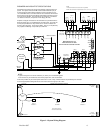
2.3 Main power Connection
The main power cable should be routed into the bottom left conduit entry.
Macurco recommends a minimum wire size of AWG18. The modular connector will accept wire from 12 to 24
AWG.
The safety ground wire should be secured to the ground stud at the bottom left of the cabinet with the lock
washer and nut supplied. Macurco recommends the use of a ring terminal for the ground connection.
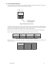
Refer to Table 2-1 for DVP-120 power connections.
The line and neutral wires should be stripped 1/4 in. (6.5 mm), insert the wire into the wire cavity of the
modular connector and tighten the screw clamp. Ensure that the wire cannot be easily pulled from the
connector. Plug the modular connector into J4 on the PCB and ensure that it latches into the header properly.
Signal Terminal Connection
Line (120/220/240/250 VAC) J4-3
Neutral J4-1
Ground Ground Stud
Table 2-1 Main Power Connections
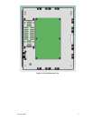
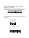
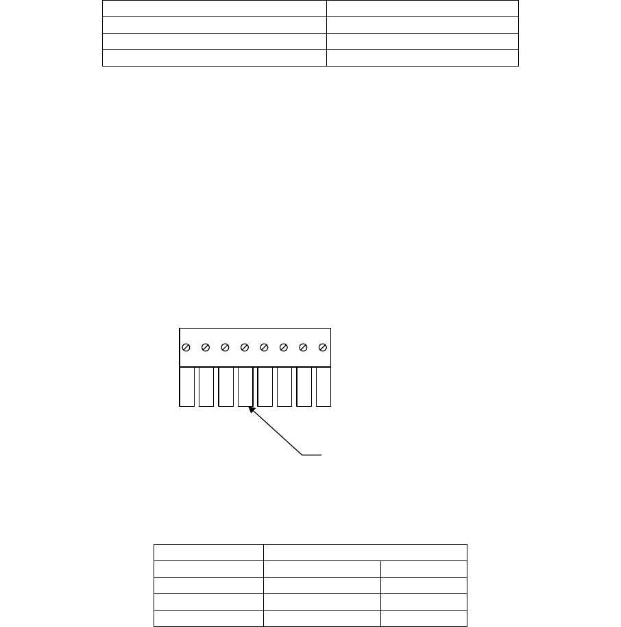
2.4 Remote Sensor Connection
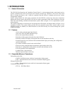
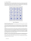
Each remote sensor is connected by a four-wire connection – two wires for DC power and two wires for the 4 –
20 mA loop connection. The sensors are connected to the control panel PCB with modular connectors, two
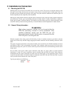
sensors per connector. See Figure 2-1 for a view of a typical sensor connector. Refer to Table 2-2 for wire size
recommendations.
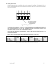
Figure 2-1 Sensor Interface Connector
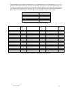
Wire gauge Maximum Run Length (ft.)
(feet) (meters)
18 500 152
16 800 244
14 1250 381
Table 2-2 Recommended Wire Gauge
Insert this face of connector
into mating connector on
control circuit board.
CH n +24 Vdc
CH n +20ma ILOOP
CH n +24V RET
CH n+1 +24 Vdc
CH n ILOOP RET
CH n+1 ILOOP RET
CH n+1 +24V RET
CH n+1 +20ma ILOOP
1 8