


Revision 0.07
13
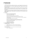
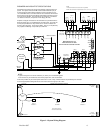
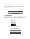
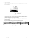
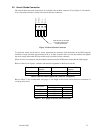
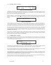
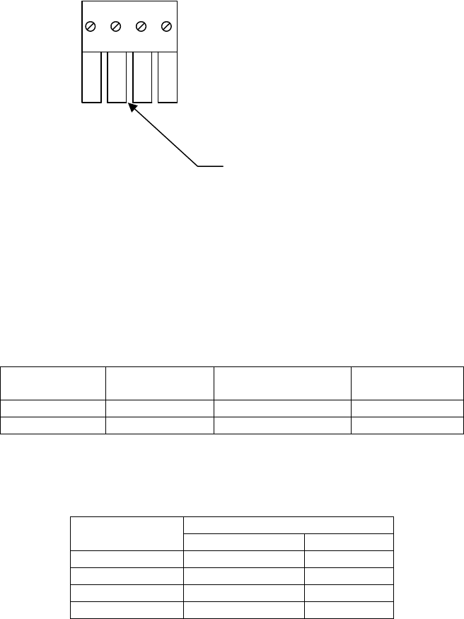
2.6 Horn & Strobe Connection
The external horn and strobe connections are available at the modular connector J5 (see Figure 2-3 for details).
J5 as a 4-position connector, similar to the sensor interface connectors.
Insert this face of connector
into mating connector on
control circuit board.
Strobe -
Horn -
Horn +
Strobe +
1 4
Figure 2-3 Horn & Strobe Connector
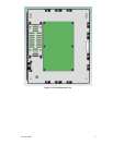
To install the wiring for the horn or strobe, disconnect the connector from the header on the PCB. Strip the
insulation of each wire back approximately 0.25 in. (6 mm), insert the bare wire into the terminal and tighten
the screw clamp. Ensure that the wire cannot easily be pulled from the connector.
When all wires are connected, seat the modular connector into the PCB header; ensure that the latch engages.
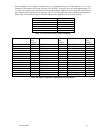
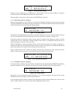
Refer to Table 2-6 for signals, connector and terminal assignment for the horn and strobe.
Signal Name Connector-Pin
Number
Signal Name Connector-Pin
Number
Horn + J5-1 Strobe + J5-3
Horn - J5-2 Strobe - J5-4
Table 2-6 Horn & Strobe signals and Connector Assignments
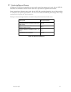
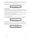
Refer to Table 2-7 for recommended wire gauge vs. run length for the horn & strobe functions (maximum 2.5
volt drop in the wire).
Maximum Run Length (ft.)
Wire gauge
(feet) (meters)
24 200 61
22 340 103
20 480 147
18 850 215
Table 2-7 Wire gauge for Horn & Strobe functions