


Revision 0.07
12
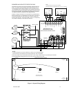
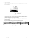
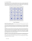
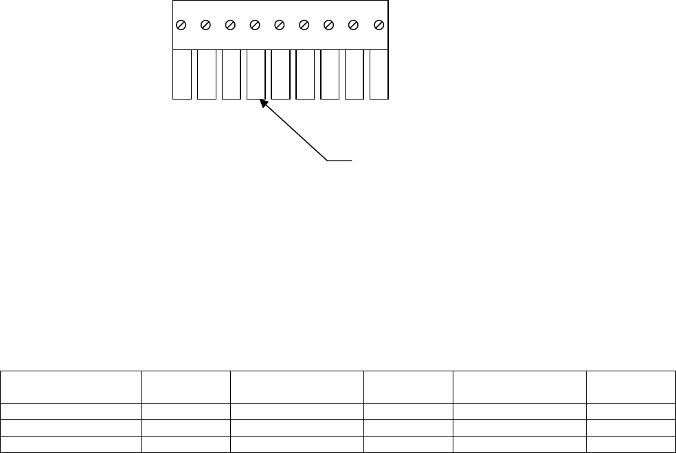
2.5 Relay Connection
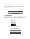
All poles of the three relays are available at the modular connector J2 (see Figure 2-2 for details). J2 is a 9-
position variant of the high voltage modular connector used for power input. Each terminal can accommodate a
wire size 12 to 24 AWG.
Insert this face of connector
into mating connector on
control circuit board.
R2 NO
R2 C
R3 NO
R1 NC
R3 NC
R1 C
R2 NC
R1 NO
1
9
R3 C
Figure 2-2 Relay Connector
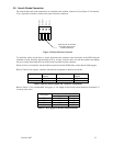
To install the wiring for the relays, disconnect the connector from the header on the PCB. Strip the insulation of
each wire back approximately 1/4 in. (6.5 mm), insert the bare wire into the terminal and tighten the screw
clamp. Ensure that the wire cannot easily be pulled from the connector.
Note that the panel configuration can designate Relay-1 as an ALARM signal relay. Relay-2 and Relay 3 are
general purpose in function.
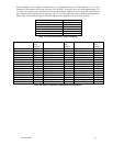
Refer to Table 2-5 for output signals, connector and terminal assignment for all three relays.
Signal Name Connector-
Pin Number
Signal Name Connector-
Pin Number
Signal Name Connector-
Pin Number
Relay 1 NC J2-1 Relay 2 NC J2-4 Relay 2 NC J2-7
Relay 1 NO J2-2 Relay 2 NO J2-5 Relay 2 NO J2-8
Relay 1 Common J2-3 Relay 2 Common J2-6 Relay 2 Common J2-9
Table 2-5 Relay Interface Signals and Connector Assignments