


Revision 0.07
15
3 Operation
3.1 Initial Operating Mode
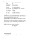
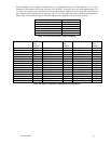
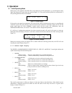
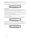
When power is first applied to the DVP-120, a few simple tests will be performed, e.g. cycle through all status
lights, and display the system name and model # (Figure 3-1). The system will then proceed to normal mode, if
the operating parameters have been entered.
D
V
P
-
1
2
0
V
e
r
1
.
0
1
Figure 3-1 Model Display
If the user has not entered any parameters, the system WILL NOT be monitoring the sensors or controlling the
ventilation system. The relays will be in the not actuated state and the horn and strobe outputs will be off. The
power status light will show NORMAL (steady green) and the system will immediately enter the
CONFIGURATION mode, see section 3.2 for details to set the configuration parameters.
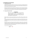
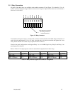
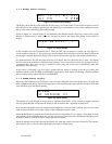
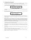
If a valid set of configuration parameters have been entered the panel will wait for all sensors to warm up.
During this time, the display will show a count down, minutes and seconds, until the end of the warm-up period,
Figure 3-2.
D
V
P
-
1
2
0
V
e
r
.
1
.
0
1
W
a
r
m
-
u
p
2
:
3
0
Figure 3-2 Warm-Up display
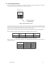
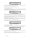
During the warm-up period, the keypad will be locked. When the warm-up period ends, the LCD will start
showing the normal display, Figure 3-4.
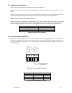
3.1.1 Status Light Display
The POWER, ALARM/WARNING, SILENCE, RELAY 1, RELAY 2 and RELAY 3 status lights indicate the
system status and provide the following data:
? POWER
? Green (steady) – Power is good and there are no trouble indications
? Yellow (steady) – Trouble is indicated by a transducer or the panel itself
? ALARM/WARNING
? Off – All indicated gas levels are below the warning level
? Red (steady) – One or more gas levels is at or above the alarm level
? Amber (steady) – One or more gas levels is at or above the warning level
? SILENCE
? Off –There are no silenced alarms or warnings
? Red (flashing) –There are alarms and/or warnings that have been silenced (gas levels may
or may not still be at alarm or warning levels)
? RELAY 1
? Off – Relay 1 is not on
? Green (steady) – Relay 1 is on
? RELAY 2
? Off – Relay 2 is not on
? Green (steady) – Relay 2 is on
? RELAY 3
? Off – Relay 3 is not on
? Green (steady) – Relay 3 is on
The overall system status is visible at a distance via the status lights as described above. More detailed system
information is displayed on the LCD, which can show the status of each relay and sensor. A typical status
display is shown in Figure 3-4.