


Revision 0.07
29
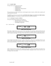
3.3.7 Configure Zones Submenu
The DVP-120 ventilation control can support up to three zones. The zone functionality makes the DVP-120
very flexible. For example, each zone can be configured to monitor a separate set of 4 sensors and control a
single relay.
Another control scheme uses one zone to monitor all sensors and turn one relay on at a relatively low gas
concentration. A second zone monitors the same sensors and turns on a second relay if the gas concentration
reaches a higher level. The third zone can also monitor the same relays turning the last relay on as a signaling
device to a live monitor station, as well as turning on the external horn and strobe, under the assumption that the
ventilation system is not working.
In addition to controlling the relays based on the gas concentration, each zone can have a timed function, e.g.
turn on low volume ventilation fans at 7:00 AM and turn them off at 8:00 PM.
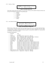
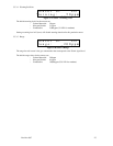
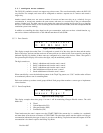
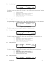
3.3.7.1 Zone Controls
Z
o
n
e
1
C
o
n
t
r
o
l
s
R
1
R
2
R
3
H
4
S
5
Figure 3-41 Zone Controls
This display example shows that Zone 1 is configured to control all of the relays plus the horn and the strobe.
Each of the relays, the horn and the strobe can be removed from (or added to) the zones control by pressing the
indicated digit key. By default, all three zones are configured not to control any devices. When a new panel is
first powered up this display will not show the digits, only the underlined positions.
The digit controls are:
– 1 Relay 1 added/removed form the zone’s control
– 2 Relay 2 added/removed form the zone’s control
– 3 Relay 3 added/removed form the zone’s control
– 4 Horn added/removed form the zone’s control
– 5 Strobe added/removed form the zone’s control
When controlled by a zone the default horn pattern is the Triple Tap pattern, see 3.3.8.7 and the strobe will turn
on continuously when a zone is controlling them.
Each zone can have up to three control groups defined. Each group either monitors a sensor type or implements
a timer function.
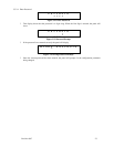
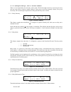
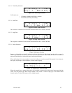
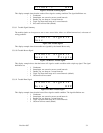
3.3.7.2 Zone Group Mode
Z
1
G
r
o
u
p
1
N
O
2
S
e
n
s
o
r
T
y
p
e
:
2
Figure 3-42 Zone Group Type
This display example shows that group 1 in zone 1 will be monitoring Nitrogen Dioxide sensors. The valid
Modes are:
– 0 Timed
– 1 Carbon Monoxide (CO)
– 2 Nitrogen Dioxide (NO2)
– 3 Combustible (EX)
Timed mode turns the zone’s outputs on at the START TIME if the current day is a weekday (or a weekend)
and turns them off at the next occurrence of STOP TIME. The other three modes turn the outputs on if the gas
concentration indicated by that type of sensor is at or above the Rising Trip Point and turns the outputs off if the
concentration is less than or equal to the Falling Trip Point.