Revision 0.07
18
A
L
A
R
M
S
I
L
E
N
C
E
D
F
O
R
5
M
I
N
U
T
E
S
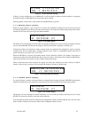
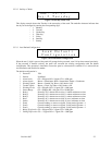
Figure 3-7 Alarm Silenced message
If Relay 1 has be configured as an ALARM relay it will be turned on when an alarm condition is recognized
and will be turned off when all audio indicators have been silenced.
Silencing applies to the cause(s) of the alarm when the HUSH key is pressed.
3.1.5 Warning Status Display
When any sensor indicates a gas level that is at or above the configured warning level for the sensor, the panel
will enter WARNING mode during which the internal buzzer will sound, the alarm/warning lamp will be amber
and the LCD will show the sensor type and channel number.
W
A
R
N
I
N
G
C
O
S
E
N
S
O
R
0
2
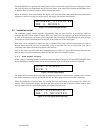
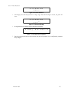
Figure 3-8 Warning display
The display will cycle through all sensors that are signaling warning levels, at five seconds per display. Pressing
any key (except HUSH) will advance the display to the next sensor that is signaling a warning level.
If the buzzer and/or an external horn and/or external strobe are connected and configured to signal a warning
condition, they will also sound when a warning condition occurs. There is a configurable delay for the horn or
strobe will sound, see sections 3.3.5.3 and 3.3.6.3.
When the HUSH key is pressed, the internal buzzer will be silenced for fifteen (15) minutes. If the horn or
strobe turn on delays have not finished then they will also be silence. If the delays have finished, the HUSH key
must be held for three (3) seconds in order to silence the horn and strobe.
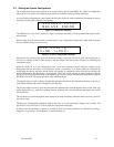
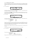
When all indicators have been silenced, the display will show that warnings have been silenced for fifteen
minutes. After any key is pressed (or five seconds) the display will return to normal mode.
W
A
R
N
I
N
G
S
I
L
E
N
C
E
D
F
O
R
1
5
M
I
N
U
T
E
S
Figure 3-9 Warning Silenced message
3.1.6 Trouble Status Display
If a sensor indicates a trouble, or the panel detects an internal fault, the panel will enter TROUBLE mode during
which the internal buzzer will sound, the power lamp will be yellow and the LCD will show the problem.
T
R
O
U
B
L
E
C
O
S
E
N
S
O
R
0
2
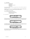
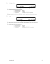
Figure 3-10 Trouble display
The display will cycle through all trouble indications, at five seconds per display. Pressing any key (except
HUSH) will advance the display to the next trouble indicator.
If an external horn and/or strobe are connected and configured to signal a trouble condition, they will also sound
when a trouble condition occurs, after a delay if that configuration option is used.


