


Revision 0.07
2
TABLE OF CONTENTS
1 INTRODUCTION ....................................................................................................................................... 5
1.1 General Information ........................................................................................................................... 5
1.2 Features .............................................................................................................................................. 5
1.3 Compatible Macurco Transducers...................................................................................................... 5
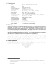
1.4 Specifications ..................................................................................................................................... 8
1.5 Warranty............................................................................................................................................. 8
1.6 Return Instructions ............................................................................................................................. 8
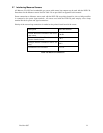
2 Installation & Connection ............................................................................................................................ 9
2.1 Mounting the DVP-120 ...................................................................................................................... 9
2.2 General Wiring Information............................................................................................................... 9
2.3 Main power Connection ................................................................................................................... 10
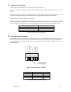
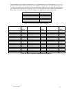
2.4 Remote Sensor Connection .............................................................................................................. 10
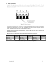
2.5 Relay Connection ............................................................................................................................. 12
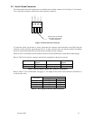
2.6 Horn & Strobe Connection............................................................................................................... 13
2.7 Interfacing Macurco Sensors............................................................................................................ 14
3 Operation.................................................................................................................................................... 15
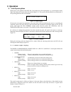
3.1 Initial Operating Mode ..................................................................................................................... 15
3.1.1 Status Light Display..................................................................................................................... 15
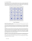
3.1.2 User Interface............................................................................................................................... 16
3.1.3 Normal Status Display................................................................................................................. 17
3.1.4 ALARM Status Display............................................................................................................... 17
3.1.5 Warning Status Display ............................................................................................................... 18
3.1.6 Trouble Status Display................................................................................................................. 18
3.2 Ventilation control............................................................................................................................ 19
3.2.1 Zone Signal Display..................................................................................................................... 19
3.3 Setting the System Configuration..................................................................................................... 20
3.3.1 System Menu ............................................................................................................................... 21
3.3.2 Configure System Submenu ........................................................................................................ 21
3.3.3 Configure Sensors Submenu........................................................................................................ 24
3.3.4 Configure Relays, Horn & Strobe Submenu................................................................................ 26
3.3.5 Configure Horn Submenu............................................................................................................ 27
3.3.6 Configure Strobe Submenu.......................................................................................................... 28
3.3.7 Configure Zones Submenu .......................................................................................................... 29
3.3.8 Configure Signals Submenu ........................................................................................................ 32
4 Troubleshooting ......................................................................................................................................... 36
4.1 System Status Light Flashing ........................................................................................................... 36
4.1.1 Input Channel Trouble................................................................................................................. 36
4.1.2 Internal Controller Board Trouble ............................................................................................... 36
4.2 Timed ventilation problem ............................................................................................................... 36
4.3 No Power.......................................................................................................................................... 37
4.4 LCD Display unreadable .................................................................................................................. 37
4.4.1 Hold the MENU key for three (3) seconds. ................................................................................. 37
4.4.2 Press the UP and DOWN cursor keys to change the LCD contrast............................................. 37
4.4.3 Press any other key to exit the contrast-setting mode.................................................................. 37
4.5 The Keypad does not respond (LCD shows KEYS LOCKED)........................................................ 37
4.6 After a power failure......................................................................................................................... 37
LIST OF FIGURES
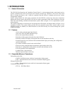
Figure 1-1 System Wiring Diagram....................................................................................................................... 6
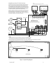
Figure 1-2 DVP-120 Internal View....................................................................................................................... 7
Figure 2-1 Sensor Interface Connector................................................................................................................ 10
Figure 2-2 Relay Connector................................................................................................................................. 12
Figure 2-3 Horn & Strobe Connector .................................................................................................................. 13
Figure 3-1 Model Display.................................................................................................................................... 15
Figure 3-2 Warm-Up display............................................................................................................................... 15
Figure 3-3 Keypad layout.................................................................................................................................... 16