


Z(f) Constant Output Impedance Design
52 315889-002
frequency applied by the application. Hence a better method is needed to extract the
impedance profile with the VR operating. The following sections introduce the theory
behind using a VTT tool to create an impedance profile for the VR system.
A.2 Voltage Transient Tool (VTT) Z(f) Theory
The following expression is the definition of impedance as a function of frequency
looking back from the VTT tool into the filter network and VRM.
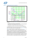
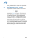
The representation of the corresponding Fourier spectra of the voltage and current
responses are shown in Figure A-2. The first harmonic values from the Fast Fourier
Transform (FFT) are used in the calculation of Z(f). The ratio of the two, yields the
impedance at a given frequency, f. By sweeping the VTT generated load transient
repetition rate, I(t), over the desired region of interest, additional points are estimated
on the impedance profile to obtain a near continuous impedance spectrum plot.
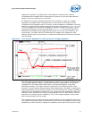
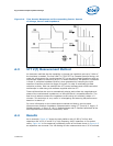
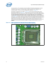
In the VTT tool, the die voltage, V(t), is brought out through a pair of non-current
carrying remote sense pins, tied to the Vcc and Vss power plane and measured on the
VTT tool substrate. The current, I(t), is a differential voltage measured across the
current shunt resistors in the VTT tool. The oscilloscope's math function is used to
convert the time domain voltage droop and current measurements into their
corresponding frequency domain spectrum. Since the FFT of the actual response
waveforms are calculated, perfect square waves of current are not needed as a
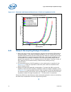
stimulus. The accuracy and frequency response of this method is limited to the current
shunt resistor's accuracy and the shunt's parasitic inductance. Parasitic inductance in
the current shunt resistors will over estimate the actual current and hence the method
will under estimate the impedance at frequencies where the inductive voltage drop
dominates the resistive voltage drop. The 50 pH of parasitic inductance in the VTT
causes an over estimation of current for frequencies over 1 MHz and an under
estimation of impedance. This can be corrected by post processing of the data and
removing the inductive voltage spike.
))((
))((
)(
tIFFT
tVFFT
fZ =