


315889-002 51
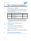
Z(f) Constant Output Impedance Design
capacitors in parallel. The effect of the mid frequency resonant point must be
investigated and validated with Vdroop testing to ensure any current load transient
pattern, does not violate the V
min
load line.
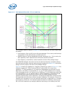
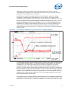
By defining the output impedance load line over a frequency range, the voltage
regulation or voltage droop is defined at any current level as the output current
multiplied by the impedance value. Currently, output impedance is validated in the time
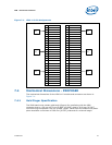
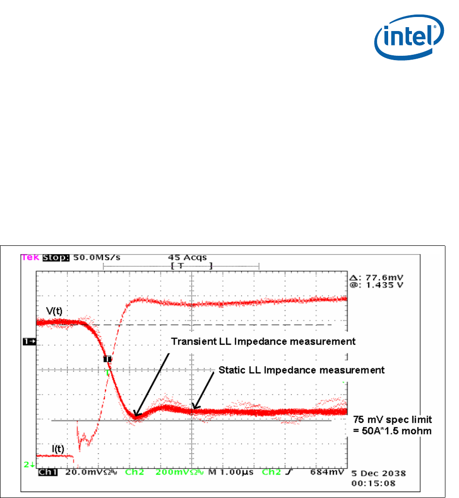
domain by measuring the voltage response to a known current step. In Figure A-1, the
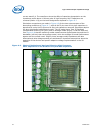
VTT tool replaces the CPU and the package for platform validation purposes. Typical
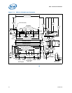
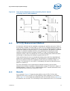
measured voltage and currents are depicted in Figure A-3. The transient load line is
defined as the voltage droop magnitude during the current rise time divided by the
current step. The static load line is defined as the voltage level magnitude, after
settling, divided by the current step. It is desired to have both the transient and static
load line equal.
The static and transient load line measurements, measure the quality of different parts
of the voltage regulator design. The transient load line is governed by the parasitic
impedances in the output filter board layout, decoupling capacitors, and power
distribution network. The static load line is governed by the PWM controller's AVP
accuracy. The time domain Vdroop testing method gives pass, fail data on meeting the
target specification, but gives little insight as to how to improve the voltage regulator's
response. It can be difficult to determine if you need more bulk capacitance, more high
frequency MLCC capacitance or higher loop bandwidth from the time domain Vdroop
waveforms. By measuring the impedance, Z(f) of the voltage regulator, these trade-
offs and optimizations can be made.
The impedance can be measured with a network analyzer, but the network analyzer can
only measure the passive filter components and will not show the effects of the VR loop
bandwidth and AVP. Also MLCC capacitors impedance varies with DC bias and AC ripple
Figure A-3. Time Domain Response of a Microprocessor Voltage Regulator