Output Voltage Requirements
12 315889-002
The continuous load current (ICCTDC) can also be referred to as the Thermal Design
Current (TDC). It is the sustained DC equivalent current that the processor is capable
of drawing indefinitely and defines the current that is used for the voltage regulator
temperature assessment. At TDC, switching FETs may reach maximum allowed
temperatures and may heat the baseboard layers and neighboring components. The
envelope of the system operating conditions, establishes actual component and
baseboard temperatures. This includes voltage regulator layout, processor fan
selection, ambient temperature, chassis configuration, etc. To avoid heat related
failures, baseboards should be validated for thermal compliance under the envelope of
the system’s operating conditions. It is proposed that voltage regulator thermal
protection be implemented for all designs (Section 6.2).
The maximum load current (I
CCMAX) represents the maximum peak current that the
processor is capable of drawing. It is the maximum current the VRM/EVRD must be
electrically designed to support without tripping any protection circuitry.
The maximum step load current (IccStep) is the max dynamic step load that the
processor is expected to impose on its Vcc power rail within the Iccmin and Iccmax
range, where the Iccmin is the processor’s min load, constituted by its leakage current.
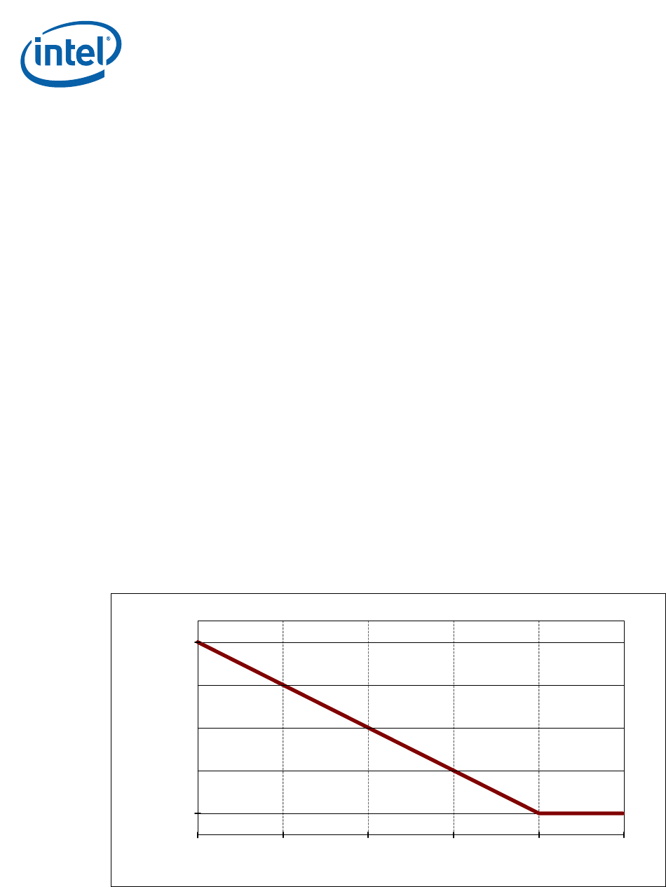
The amount of time required by the VR to supply current to the processor is dependent
on the processor’s operational activity. As previously mentioned, the processor is
capable of drawing IccTDC indefinitely; therefore, the VR must be able to supply
(I
CCTDC) indefinitely. Refer to Figure 2-1 for the time durations required by the VR to
supply current for various processor loads.
It is expected that the maximum load current (I
CCMAX) can be drawn for periods up to
10 ms. Further, it is expected that the load current averaged over a period of
100 seconds or greater, will be equal to or less than the thermal design current
(I
CCTDC).
Table 2-2 shows the ICC guidelines for any flexible motherboard (FMB) frequencies
supported by the VRM/EVRD 11.0 in Table 1-1. For designers who choose to design
their VR thermal solution to the I
CCTDC current, it is recommended that voltage
regulator thermal protection circuitry be implemented (see Section 6.2).
Figure 2-1. VRM/EVRD 11.0 Load Current vs. Time
Icc MAX
Icc TDC
0.01 0.10 1.00 10.00 100.0 1000.0
Time Duration (s)
Sustained Current (A)


