315889-002 11
Output Voltage Requirements
2 Output Voltage Requirements
2.1 Voltage and Current - REQUIRED
There will be independent selectable voltage identification (VID) codes for the core
voltage regulator. The VID code is provided by the processor to the VRM/EVRDs, which
will determine a reference output voltage, as described in Section 3.2. As previously
mentioned, the VR 11.0 controller will support two VID tables:
1. An extended 7-bit VR 10.x table, ranging from 0.83125 V to 1.6 V
2. An 8-bit VR11.0 linear table ranging from 0.03125 V to 1.6 V (usable range 0.5 V-
1.6 V).
For Dual-Core Intel Xeon Processor 7000/7100/7200/5000/5100/5200 Series -based
servers and Quad-Core Intel Xeon Processor 7300/5300/5400 Series -based servers/
workstations, the VID bits utilization will be as shown in the table below. Section 2.2
and Section 2.3 specify deviations from the VID reference voltage.
The load line tolerance in Section 2.2 shows the relationship between Vcc and Icc at the
die of the processor.
The VRM/EVRD 11.0 is required to support the following:
• A maximum continuous load current (I
CCTDC) of 130 A.
• A maximum load current (ICCMAX) of 150 A peak.
• A maximum load current step (I
CCSTEP), within a 1 µs period, of 100 A.
• A maximum current slew rate (dI
CC/dt) of 1200 A/µs at the lands of the processor.
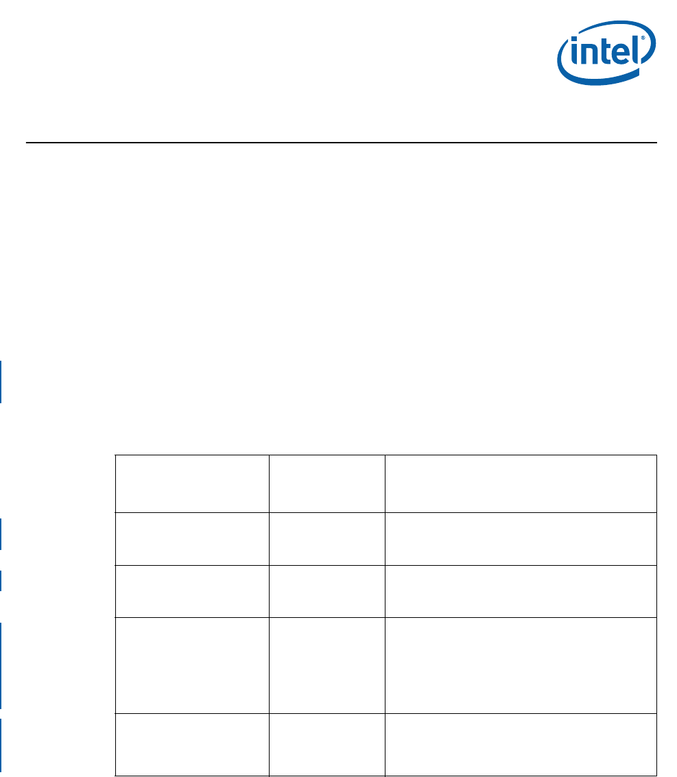
Table 2-1. Processor VID signal implementation
Processor Supported
VID Signals used
by Processor and
routed to VR with
Pull-Up resistors
Notes
Dual-Core Intel® Xeon®
Processor 7000/7100 Series
processor
VID[4:0,5]
(VID4=MSB
VID5=LSB)
VR10.2 mode; VID6 is not driven on the processor
package (socket 604), but should be routed on the VR
side with a pullup resistor; VR’s VID7 to be pulled
Low.
Dual-Core Intel® Xeon®
Processor 5000 Series
VID[4:0,5]
(VID4=MSB
VID5=LSB)
VR10.2 mode; Land AM5 (equivalent to platform
signal VID6) is not driven on the processor package,
but still routed to VID6 on VR side with a pullup
resistor; VR’s VID7 to be pulled Low.
Dual-Core Intel® Xeon®
Processor 5100 Series, Quad-
Core Intel® Xeon® Processor
5300 Series, Dual-Core
Intel® Xeon® Processor
5200 Series, or Quad-Core
Intel® Xeon® Processor
5400 Series processors
VID[6:1]
VR11.0 mode; Land AM2 (equivalent to platform
signal VID0) is connected to VSS on the processor
package, and routed to VID0 on VR side with a pullup
resistor; VR’s VID7 to be pulled Low.
Quad-Core Intel(R) Xeon(R)
Processor 7300 Series &
Dual-Core Intel(R) Xeon(R)
Processor 7200 Series
processors
VID[6:1]
VR11.0 mode; VID0 is not driven on the processor
package (socket 604P), but should be routed on the
VR side and pulled Low; VR’s VID7 to be pulled Low.


