4 315889-002
8.10 Safety - PROPOSED ...........................................................................................46
9 Manufacturing Considerations..................................................................................47
9.1 Lead Free (Pb Free) ...........................................................................................47
A Z(f) Constant Output Impedance Design..................................................................49
A.1 Introduction - PROPOSED ...................................................................................49
A.2 Voltage Transient Tool (VTT) Z(f) Theory ..............................................................52
A.3 VTT Z(f) Measurement Method ............................................................................53
A.4 Results.............................................................................................................53
A.5 Output Decoupling Design Procedure ....................................................................56
Figures
2-1 VRM/EVRD 11.0 Load Current vs. Time.................................................................12
2-2 Processor Vcc Overshoot Example Waveform.........................................................16
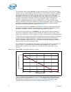
2-3 Power Distribution Impedance vs. Frequency.........................................................17
2-4 Power-On Sequence Timing Diagram....................................................................19
2-5 Processor Transition States .................................................................................21
2-6 Dynamic VID Transition States Illustration ............................................................21
2-7 Six-layer Dual-Core Intel Xeon Processor-Based Server Platform VccP
Power Delivery Impedance Model Path with 1206 Size Caps.....................................23
2-8 Eight-layer Dual-Core Intel Xeon Processor-Based Server Platform VccP
Power Delivery Impedance Model Path with 1206 Size Caps.....................................23
2-9 Eight-layer Dual-Core Intel Xeon Processor-Based Server Platform VccP
Power Delivery Impedance Model Path with 0805 Size Caps.....................................23
2-10 Dual-Core Intel Xeon 5000 Series with Intel 5400 Chipsets Platform VccP
Power Delivery Impedance Model Path - Example...................................................25
3-1 Remote Sense Routing example...........................................................................30
6-1 VRM 11.0 and Platform Present Detection .............................................................39
7-1 VRM 11.0 Pin Assignments..................................................................................43
7-1 VRM 11.0 Module and Connector..........................................................................44
A-1 Typical Intel® Microprocessor Voltage Regulator Validation Setup ............................49
A-2 Z(f) Network Plot with 1.25 mW Load Line ............................................................50
A-3 Time Domain Response of a Microprocessor Voltage Regulator.................................51
A-4 Time Domain Responses and Corresponding Fourier Spectra
of Voltage, Current and Impedance ......................................................................53
A-5 Photo of Motherboard Analyzed Showing High Frequency
MLCC Capacitors In the Socket Cavity and Bulk Capacitors......................................54
A-6 Measured Platform Impedance Profile Showing Change
in Impedance as Capacitors Are Removed.............................................................55
A-7 Designations of MLCC Cavity Capacitor Banks........................................................55
A-8 Simulated and Measured Waveforms of Platform Impedance Profile..........................56
Tables
1-1 VRM/EVRD 11.0 Supported Platforms and Processors............................................... 9
1-2 Guideline Categories ..........................................................................................10
2-1 Processor VID signal implementation ....................................................................11
2-2 Icc Guidelines ...................................................................................................13
2-3 VID_Select, LL1, LL0 Codes.................................................................................14
2-4 Impedance Z
LL
Measurement Parameter Limits ......................................................18
2-5 Startup Sequence Timing Parameters ...................................................................19


