


55Heat & Glo • XLR-PLUS-N-AU, XLR-PLUS-PB-AU • 2264-900 Rev. M • 7/12
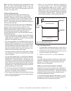
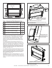
Note:The lower cover panel must be pushed all the way
down. The outer nishing anges should line up. The
replace opening must be between 15-3/4 in. (400 mm)
and 16-1/8 in. (410 mm) for the decorative fronts to t
correctly. See Figure 13.4.
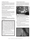
FinishandSealingJoints
All joints between the nished wall sheating and
the appliance must be sealed with non-combustible
materials. Sealants, such as caulk or mastic used to
seal the gap between the wall and the replace, should
be rated at a minimum continuous exposure to 149 °C
(300 °F). Wall board joints can be taped and sealed with
combustible drywall tape.
FinishingAroundOpeningwithGypsumWallboard
Gypsum wallboard (drywall) joints adjacent to the
replace opening require special attention to minimize
potential development of cracking. Hearth and Home
Technologies recommends the following steps to
minimize potential cracks in the nished drywall around
the replace opening:
• When installing gypsum wallboard around the replace,
install the hole for the replace opening in a single
wallboard sheet, if possible. This will minimize the joints
adjacent to the replace opening.
• The factory-supplied non-combustible board and the
gypsum wallboard must join on the structural framing,
where applicable. Wallboard and non-combustible board
should be fastened to the framing with at least 1-1/4 in.
(32 mm) long screw fasteners, located within 1-1/2 in.
(38 mm) from each corner, and at no more than 12 in.
(305 mm) intervals along the joint length.
• The wall-board joints should be nished with a Taping
Coat, followed by at least two subsequent Finish Coats
of joint compound.
• For the initial Taping Coat, it is critical that a general-
purpose chemically hardening joint compound, such as
SHEETROCK™ Brand Durabond™ Setting-Type Joint
Compound, be used to ll the joint and embed the mesh
tape. Fiberglass-mesh tape is recommended because it
will provide a more crack-resistant joint than one nished
with paper tape. Let the Taping Coat properly cure before
applying subsequent Finish Coats.
•For the second and third nishing coats, it is acceptable
to use a light-weight joint compound and standard
application, curing and sanding methods.
•Do not operate the replace during the drywall nishing
process. Allow the nish coat to cure for at least 24 hours
prior to using the appliance.
Painting
If desired nishing includes a painted wall, 100% acrylic
latex with compatible primer is recommend around the
appliance. Oil-based or standard acrylic paints may
discolor due to heat exposure.
WallboardJoint-CrackPreventionandRepair
Wallboard joints around the replace will be affected by
exposure to elevated temperatures, along with other en-
vironmental and structural factors. The specic methods
presented in the previous section will help prevent or
minimize development of cracks.
If a crack does emerge adjacent the replace, it can be
permanently repaired by lling it with spackling paste or
paintable latex caulk, followed by repainting.
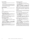
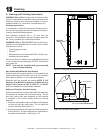
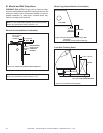
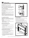
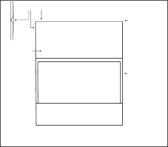
V-JOINT TO PLATERBOARD & WHITE INSULATION BOARD, BUTT JOIN EACH AND BACK FILL WITH
CORNICE CEMENT. OVERLAY JOIN WITH FIBERGLASS TAPE AND TROWEL TOP COAT OVER.
SIDE
ELEVATION
ENTIRE INSULATION
BOARD TO BE
TOP COATED
WHITE INSULATION BOARD
FIBERGLASS TAPE
ONLY ON JOINT
12 mm CLEARANCE
TO COMBUSTIBLES
Plasterboard to be adhered to lower panel using silicone
(no screws to be used).
Figure13.5WhiteInsulationBoard
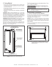
•Retain 12 mm clearance between plasterboard
and vertical sides of unit. Butt join plasterboard
and white insulation board at top of heater. USING
ONLY FIBERGLASS TAPE nish insulation board to
plasterboard as per normal plasterbaord procedures.
Ensure that top coat nish extends down to top of heater,
as indicated in diagram below. Insulation board will
remain exposed as part of the nished plaster face.
GasPipeRequirements
1. If polyethylene composite gas pipe is to be used, a
clearance of 150 mm must be maintained from all ues.
2. Polyethylene composite gas pipe must not be used as
the nal connection onto the heater.
3. Leave a 1 m. tail of 1/2 in. (13 mm) copper pipe.