


Heat & Glo • XLR-PLUS-N-AU, XLR-PLUS-PB-AU • 2264-900 Rev. M • 7/12 42
11
GasInformation
A. GasPressureRequirements
Pressure requirements for XLR-PLUS-AU replaces are
shown in Table 11.1 below.
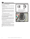
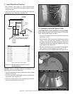
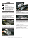
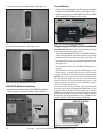
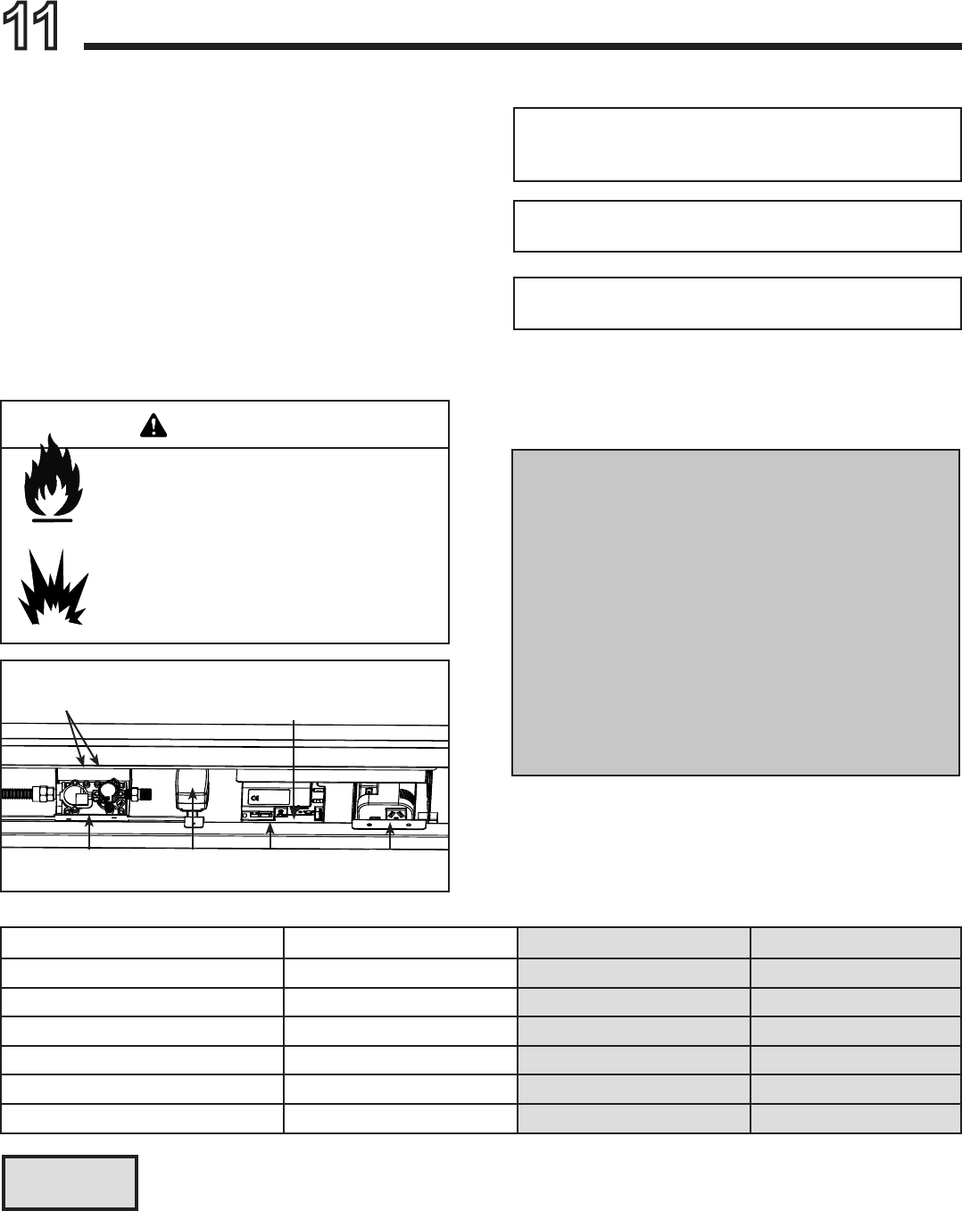
Two taps are provided on the front face of the gas control
for a test gauge connection to measure the inlet and out-
let pressures. See Figure 11.1.
The replace and its individual shut-off valve must be dis-
connected from the gas supply piping system during any
pressure testing of the system at test pressures in excess
of 3.4 kPa.
If the replace must be isolated from the gas supply pip-
ing system by closing an individual shut-off valve, it must
be of the handle-less type.
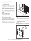
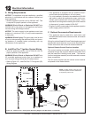
Incoming gas line should be piped into the valve compart-
ment and connected to the ISO 7-Rp 1/2 (BSP Rp 1/2)
threaded gas inlet connection on the manual shutoff valve.
Table11.1
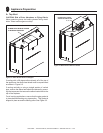
B. GasConnection
Note:Have the gas supply line installed in accordance with
local building codes by a qualied installer approved and/or
licensed as required by the locality.
Note:Before the rst ring of the appliance, the gas supply
line should be purged of any trapped air.
Note:Consult local building regulations to properly size the gas
supply line leading to the (Rp 1/2 in.) hook-up at the unit.
WARNING
Fire Risk
Explosion Risk
High pressure will damage valve.
• Disconnect gas supply piping BEFORE
pressure testing gas line at test pressures
above 3.4 kPa.
• Close the manual shutoff valve BEFORE
pressure testing gas line at test pressures
equal to or less than 3.4 kPa.
Figure11.1.ValveComponents
NaturalGas Propane Butane
Inlet Gas Pressure 1.13 - 3.40 kPa 2.75 - 3.40 kPa 2.75 - 3.40 kPa
Outlet (Manifold) Gas Pressure .80 - .95 kPa 2.36 - 2.61 kPa 2.36 - 2.61 kPa
Gas Rate .405
m3
/
h
.134
m3
/
h
.111
m3
/
h
Maximum Gas Consumption 26 MJ/h 26 MJ/h 22 MJ/h
Burner Injector DMS 42 (2.350 mm) DMS .057 (1.450 mm) DMS 55 (1.325)
Pilot Injector Ø .023 (.584 mm) Ø .014 (.356 mm) Ø .010 (.254 mm)
Columns highlighted in gray = The gas control valve supplied with this product is approved for a maximum
inlet pressure of 3.40kPa. For pressures over 3.40kPa, an in line pressure regulator must be installed
upstream from the gas control valve.
PRESSURE
TAPS
ON/OFFREMOTE
TOGGLESWITCH
VARIABLE
VALVE
6VDC
REGULATOR
8KI-CE
MODULE
AUX300CE
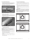
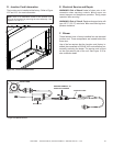
Leak test all gas line points and the gas control valve prior
to and after starting the gas appliance.
IMPORTANTNOTICE: (Items 1, 2 and 3 applies to
ALL Heat & Glo gas appliances)
1. 1/2 in. GAS LINE: Run through cavity 70 mm
above nished hearth level, NOT RIGID, NOT
CLIPPED, with minimum 500 mm into cavity and
120 mm back from plaster face.
2. PVC (COMPOSITE) GASLINE must terminate
minimum 500 mm short of gas heater. Copper pipe
MUST be the nal connection to the gas heater.
3. ISOLATING SWITCH: Location within 1 metre
of replace, subject to mantelpiece etc. Check to
ensure it remains clear of any mantelpiece instal-
lation.