


53
Heat & Glo • 6000CL-IPI-S, 6000CL-IPI-T, 8000CL-IPI-S 8000CL-IPI-T • 2165-900 Rev. S • 9/12
13
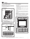
Finishing
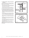
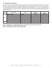
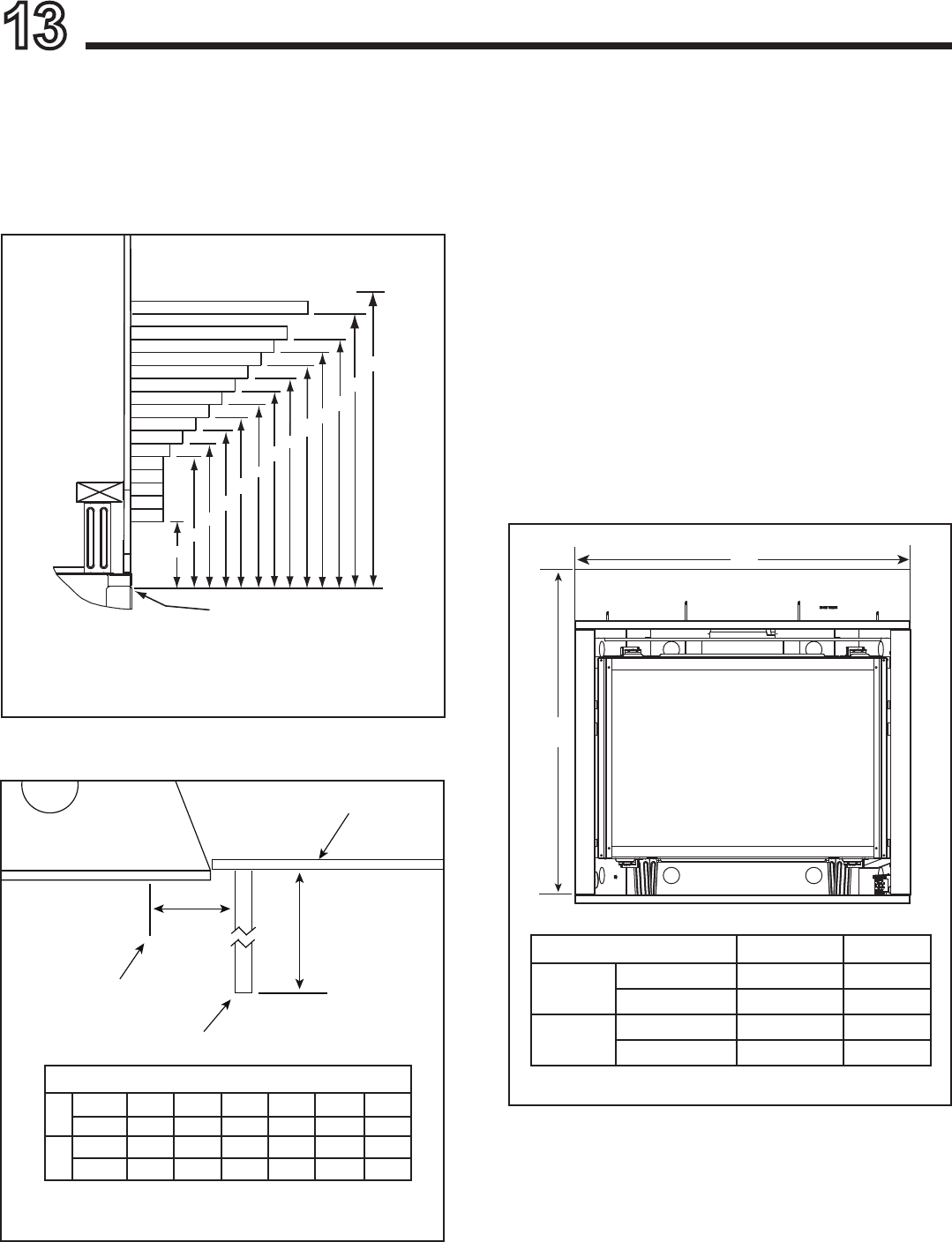
A. MantelandWallProjections
WARNING! Risk of Fire! Comply with all minimum clear-
ances as specied. Framing closer than the minimums list-
ed must be constructed entirely of noncombustible materials
(i.e., steel studs, concrete board, etc.)
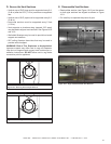
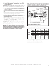
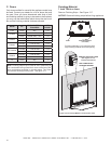
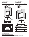
Figure13.2CombustibleMantelLegorWallProjections
(Acceptableonbothsidesofopening)
Figure13.1MinimumVerticalandMaximumHorizontal
DimensionsofCombustibles
CombustibleMantels
CombustibleMantelLegsorWallProjections
MEASUREMENTS FROM
TOP EDGE OF THE OPENING
5
10
11
12
2-1/2
13
14
15
16
17
18
19
32
TO CEILING
9
10
11
12
8
7
6
5
4
3
25
18
A
B
INTERIOR WALL
TOP VIEW
MANTEL LEG OR WALL PROJECTIONS
FIREPLACE OPENING
Note: All
measurements
in inches.
IfAminimumis____,thenBmaximumis_____.
A
Inches
2-7/16 3-7/16 4-7/16 5-7/16 6-7/16 7-7/16
Millimeters
62 87 113 138 164 189
B
Inches
1 2 3 4 5
∞
Millimeters
25 51 76 102 127
∞
Note: Measurement is taken from top of the opening,
NOT the top of the replace.
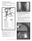
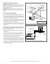
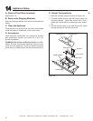
B. FacingMaterial
• Metal front faces may be covered with non-combustible
materials only.
• Facing and/or nishing materials must not interfere with
air ow through louvers, operation of louvers or doors,
or access for service.
• Facing and/or nishing materials must never overhang
into the glass opening.
• Observe all clearances when applying combustible
materials.
• Seal joints between the nished wall and appliance top
and sides using a 300ºF minimum sealant. Refer to
Figure 13.3.
WARNING! Risk of Fire! DO NOT apply combustible
materials beyond the minimum clearances. Comply with
all minimum clearances to combustibles as specied in
this manual. Overlapping materials could ignite and will
interfere with proper operation of doors and louvers.
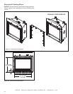
Figure13.3NoncombustibleFacingDiagram
B
A
FACTORY-INSTALLED NON-COMBUSTIBLE BOARD
DO NOT REMOVE
A B
6000
inches 39-3/4 41
millimeters 1010 1041
8000
inches 41-3/4 48
millimeters 1060 1219