


Heat & Glo • 6000CL-IPI-S, 6000CL-IPI-T, 8000CL-IPI-S 8000CL-IPI-T • 2165-900 Rev. S • 9/12
44
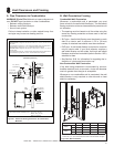
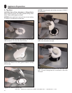
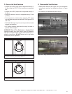
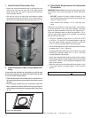
B. AssembleVentSections(SLPPipeOnly)
To attach the rst vent component to the starting collars
of the appliance:
• Attach a DVP-2SL or DVP-SLP24 adapter to the starting
collar of the appliance.
• Lock the vent components into place by sliding the pipe
section onto the collar.
• Align the seam of the pipe and seam of collar to allow
engagement. Rotate the vent component to lock into
place. Use this procedure for all vent components. See
Figure 10.5.
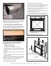
• Slide the gasket over the rst vent section and place it
ush to the appliance. This will prevent cold air inltration.
Caulk with a minimum of 300ºF continuous exposure
rating may be used to hold the part in place.
• Continue adding vent components, locking each
succeeding component into place.
• Ensure that each succeeding vent component is securely
tted and locked into the preceding component.
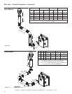
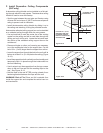
Commercial,Multi-family(Multi-levelexceedingtwosto-
ries),orHigh-RiseApplications
For Installation into a commercial, multi-family (multi-level
exceeding two stories) or high-rise applications: All outer
pipe joints must be sealed with silicone with a minimum
of 300ºF continuous exposure rating, including the slip
section that connects directly to the horizontal termina-
tion cap.
• Apply a bead of silicone sealant inside the female outer
pipe joint prior to joining sections. See Figure 10.1.
• Only outer pipes need to be sealed. All unit collar, pipe,
slip section, elbow and cap outer ues shall be sealed
in this manner, unless otherwise stated.
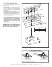
Figure10.5AddingVentingComponents
WARNING! Risk of Fire or Explosion! DO NOT break
silicone seals on slip sections. Use care when remov-
ing termination cap from slip pipe. If slip section seals
are broken during removal of the termination cap, vent
may leak.
Note: Align seams to engage pipe,
then rotate counterclockwise to lock
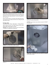
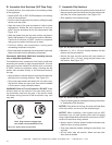
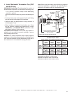
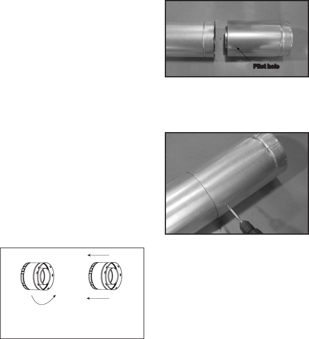
C. AssembleSlipSections
• Slide the inner ue of the slip section into the inner ue of
the pipe section and the outer ue of the slip section over
the outer ue of the pipe section. See Figure 10.6.
• Slide together to the desired length.
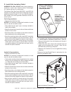
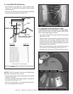
Figure10.6SlipSectionPilotHoles
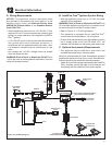
Figure10.7ScrewsintoSlipSection
Pilothole
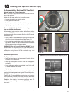
NOTICE: When installing a vent system with an HRC
termination cap, all pipe system joints shall be sealed
using a high temperature silicone with a minimum of 300ºF
continuous exposure rating sealant.
• Apply a bead of silicone sealant inside the female outer
pipe joint prior to joining sections.
• Only outer pipes are sealed, sealing the inner ue is not
required.
• All unit collar, pipe, slip section, elbow and cap outer
ues shall be sealed.
• Continue adding pipe as necessary following instructions
in “Assembling Pipe Sections.”
NOTICE: If slip section is too long, the inner and outer ues
of the slip section can be cut to the desired length.
• Maintain a 1-1/2 in. (38 mm) overlap between the slip
section and the pipe section.
• Secure the pipe and slip section with two screws no
longer than 1/2 in. (13 mm), using the pilot holes in the
slip section. See Figure 10.7.