


Heat & Glo • 6000CL-IPI-S, 6000CL-IPI-T, 8000CL-IPI-S 8000CL-IPI-T • 2165-900 Rev. S • 9/12
42
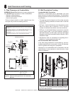
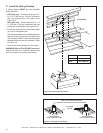
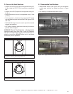
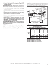
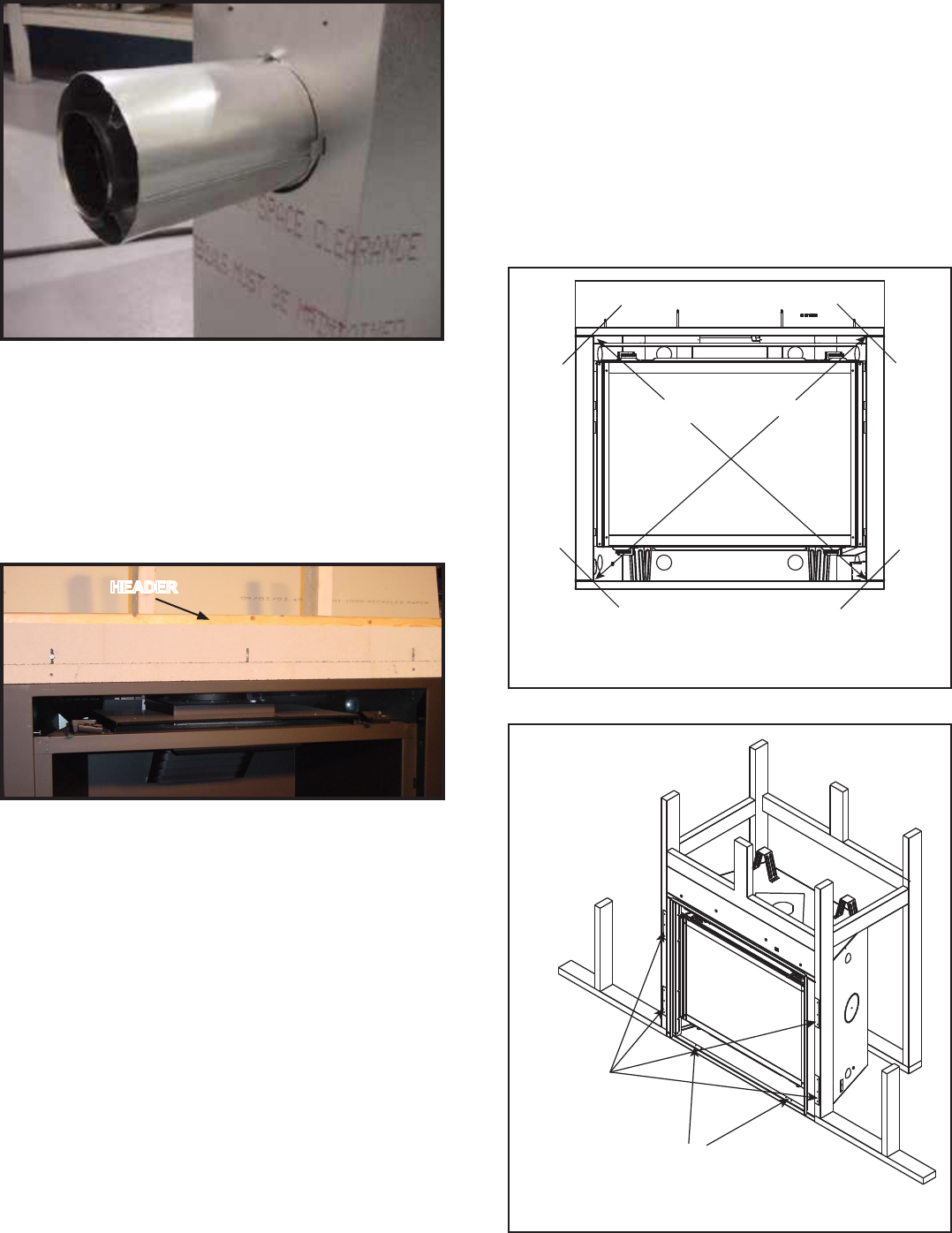
Figure9.14ProperPositioningandSecuringofanAppliance
NAILING TABS
(BOTH SIDES)
PILOT HOLES
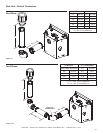
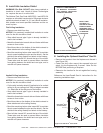
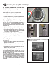
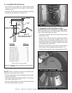
Figure9.12Non-combustibleBoard
C. InstallingtheNon-combustibleBoard
The factory supplied non-combustible board spans the dis-
tance from the top of the replace to the center of the framing
header. This board must be used. See Figure 9.12.
HEADER
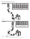
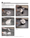
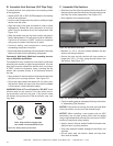
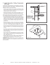
Figure9.11Attach the rst vent section (it will snap into
place). Slide the insulation gasket onto the vent section,
up against the appliance and over the tabs.
D. SecuringandLevelingtheAppliance
WARNING! Risk of Fire! Prevent contact with:
• Sagging or loose insulation
• Insulation backing or plastic
• Framing and other combustible materials
Block openings into the chase to prevent entry of blown-
in insulation. Make sure insulation and other materials
are secured.
DO NOT notch the framing around the appliance
standoffs.
Failure to maintain air space clearance may cause
overheating and re.
The diagram shows how to properly position and secure
the appliance (see Figure 9.14). Nailing tabs are provided
to secure the appliance to the framing members.
• Bend out nailing tabs on each side.
• Place the appliance into position.
• Keep nailing tabs ush with the framing.
• Level the appliance from side to side and front to back.
• “Square” the unit by securing diagonal dimensions to
within 1/4 inch of each other. See Figure 9.13.
• Shim the appliance as necessary. It is acceptable to use
wood shims underneath the appliance.
• Secure the appliance to the framing by using nails or
screws through the nailing tabs.
• Secure the appliance to the oor by inserting two screws
through the pilot holes at the bottom of the appliance.
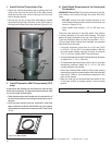
Figure9.13PositioningtheApplianceSquarely
A
B
Note:Diagonaldimensions(A)and(B)mustbewithin
1/4inchofeachother.